Tearing Apart a Perfectly Good Laptop to Fulfill a Teenage Idea
Nice laptop I got here, would be a shame if I Blood Eagled' it.
Why?
I really like the idea of a "cyberdeck", a compact computer put together from spare hardware and a dream of actually using it for something practical.
From the device used in — any — Call of Duty to call in a Kill Streak, to basically anything in CyberPunk 2077. Something about a portable computer that does not look like your regular laptop tickles my brain in a way I can't explain.
But the best I can come up with is; ✨aesthetics.💫
And recently, due to a good colleague (and a decent friend) gifting me a laptop he didn't use, nor care for, with the explicit permission to — "do what you want with it I don't care" — I was given the opportunity to fulfill this dream I had from when I was around 13 years old.
Let's get started.
Parts, Materials and Tools
Sacrificial Laptop
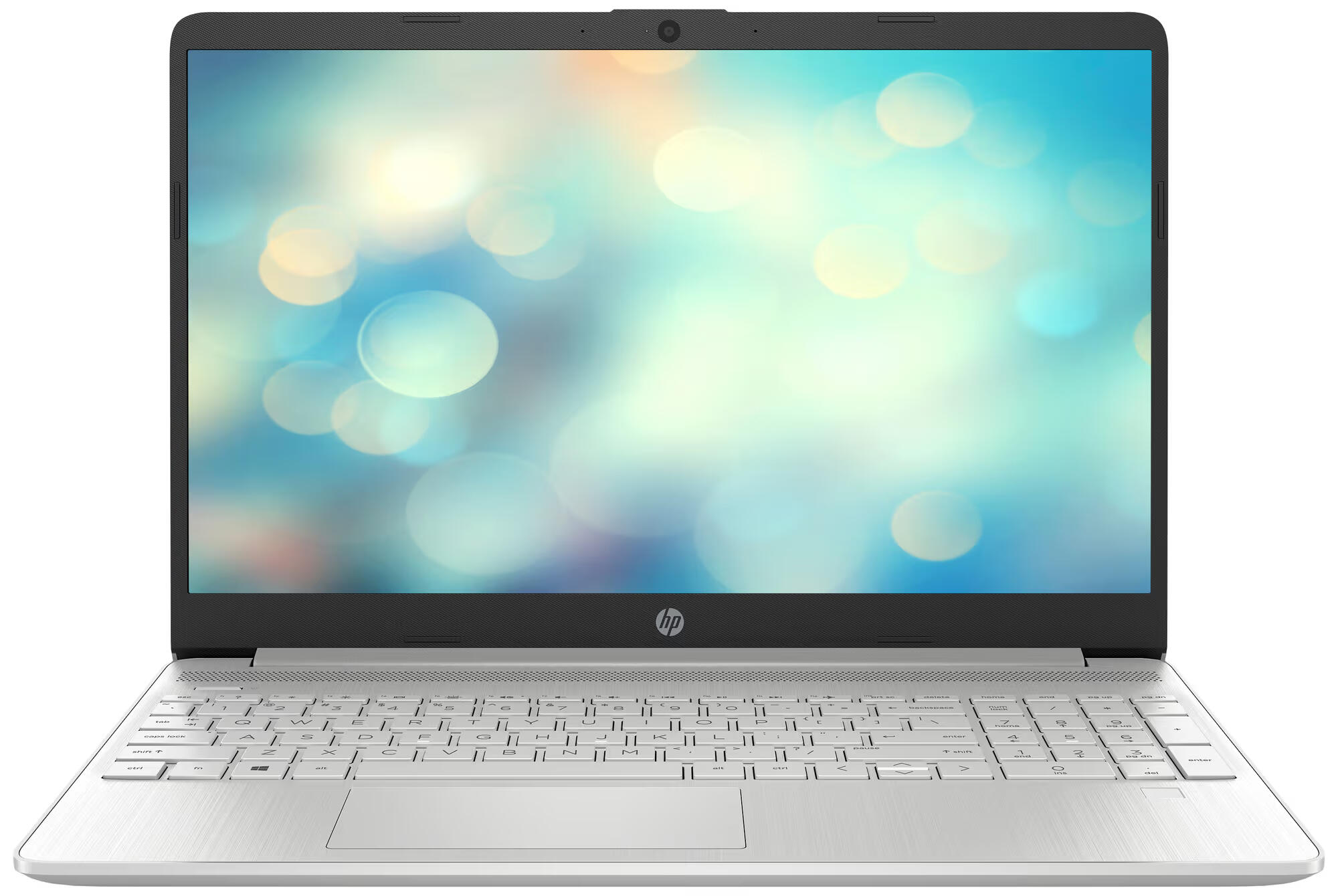
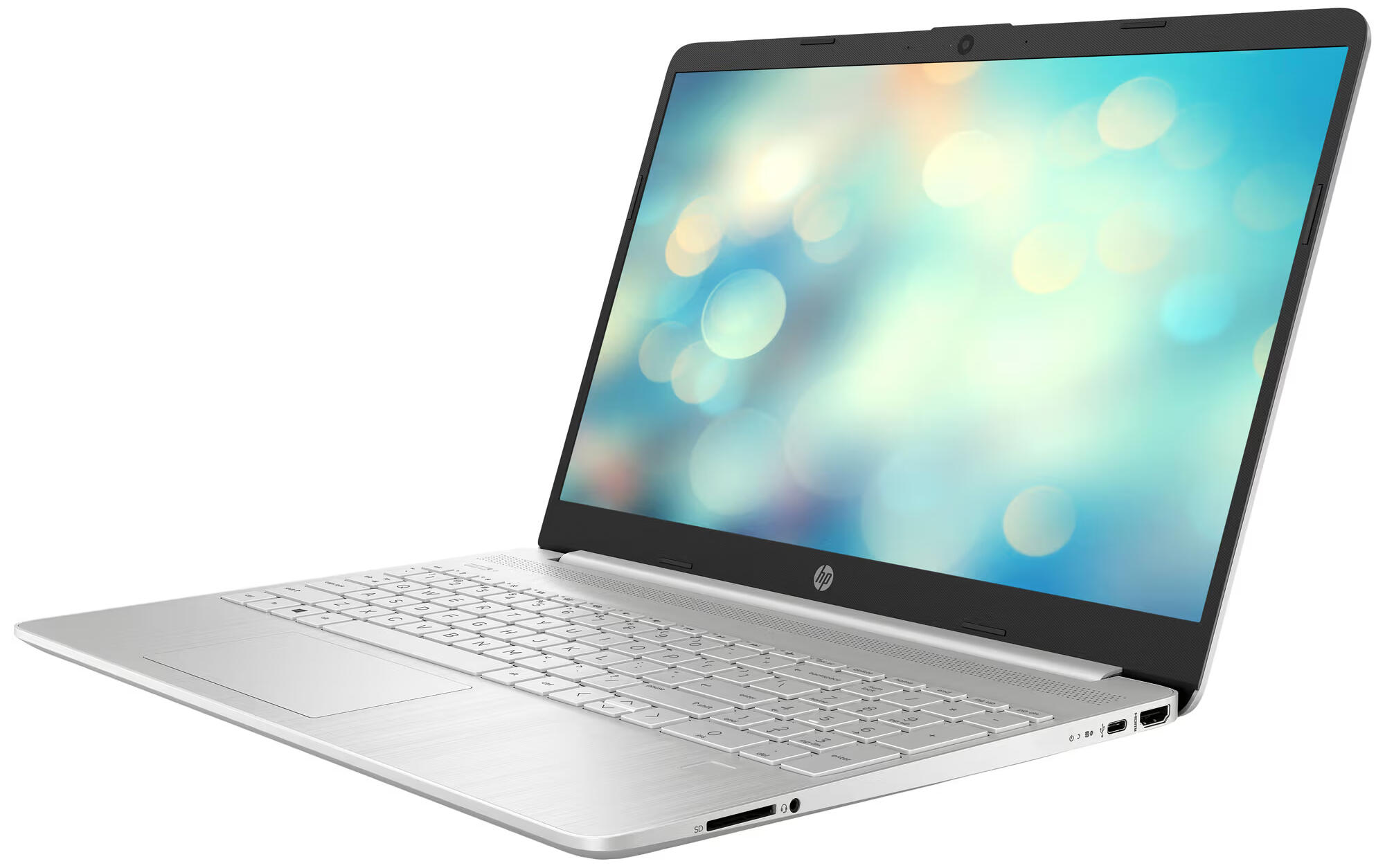
A HP 15.6 inch... it really doesn't have a name, so make of this what you will: 15s-eq2822no, sku: 4a6m6ea.
- CPU: AMD Ryzen 5 5500U 6 cores, 4GHz, with integrated Radeon graphics
- RAM: x1 8GB 3200MHz DDR4 with room for one more
- SSD: 256GB M.2 NVMe
- DISPLAY: 15.6 inch 1080p, FHD SVA
It even has a decent selection of ports.
- x1 USB-C 3.2 gen 1
- x2 USB-A 3.2 gen 1
- x1 HDMI 1.4
- x1 SD Card reader
- x1 Headphone / Microphone combo 3.5mm
- x1 Barrel charger, ewww
As well as WiFi 6 and Bluetooth 5.2.
What makes me unapologetically tear this POS apart, is the chassis. It's abhorrent. A shame. How the hell dare HP even put their logo on this thing? The plastic creaks if I open a window on the opposite end of the house. The keyboard makes me hate coding. And the display make me wish my eyesight was worse to avoid even having to deal with adjusting the lid in just the right angle for me to see my Minecraft house on fire.
I digress.
The specs are decent, I dare say the CPU is good for the price (free). And, damn, it has a better port selection than my 33.000kr (NOK) [1] Lenovo X1 Carbon Gen. 10.
Antennas
I messed up the antenna cables later in the article, so I ordered some of Aliexpress — 5Pcs/Lot WiFi 2.4G High Gain Built-in Flexible FPC Soft Antenna ZigBee Bluetooth Module Ipx4 Patch Antenna IPX to FPC Antenna — lord almighty.
Chassis / Plate Material
Some leftover acrylic sheet, 4mm, thick enough to cover the screw heads (more about that later).
Screws, Washers, Nuts and Standoffs
M2 and M3 Stainless Steel Hex Screws, that's at least what the Aliexpress product page said. Washers
to even out the gaps between the PCBs and the acrylic, and nuts to tighten things down. M3 nylon standoffs that I got from Mr. Colleague,
was used to make space in this acrylic & PBJ PCB sandwich.
Glue
Loctite, universal plastic glue. I checked before hand; it's compatible with the plastic acrylic is made of; polymethyl methacrylate (PMMA), try saying that five times.
Double Sided Tape
Whatever my father brought home from work thirteen years ago. It's about 1mm thick and a little stretchy. Can probably be used to re-attach your head in a pinch.
Tools Used
When the project was completed (until I decide it weren't of course) I ended up using;
- Jigsaw
- Drill with drillbits and a 44mm hole saw
- Bench Top Drill Press
- Sander
- Sandpaper, 120 and 400 grit
- Dremel with sanding bit
- Quick Action Clamps
- Screwdriver with bits
- Blue painters tape
- Couple of large plastic crates
StoicismThe patience of a saint
Let's Do Some Work
Tearing the Shitter Apart
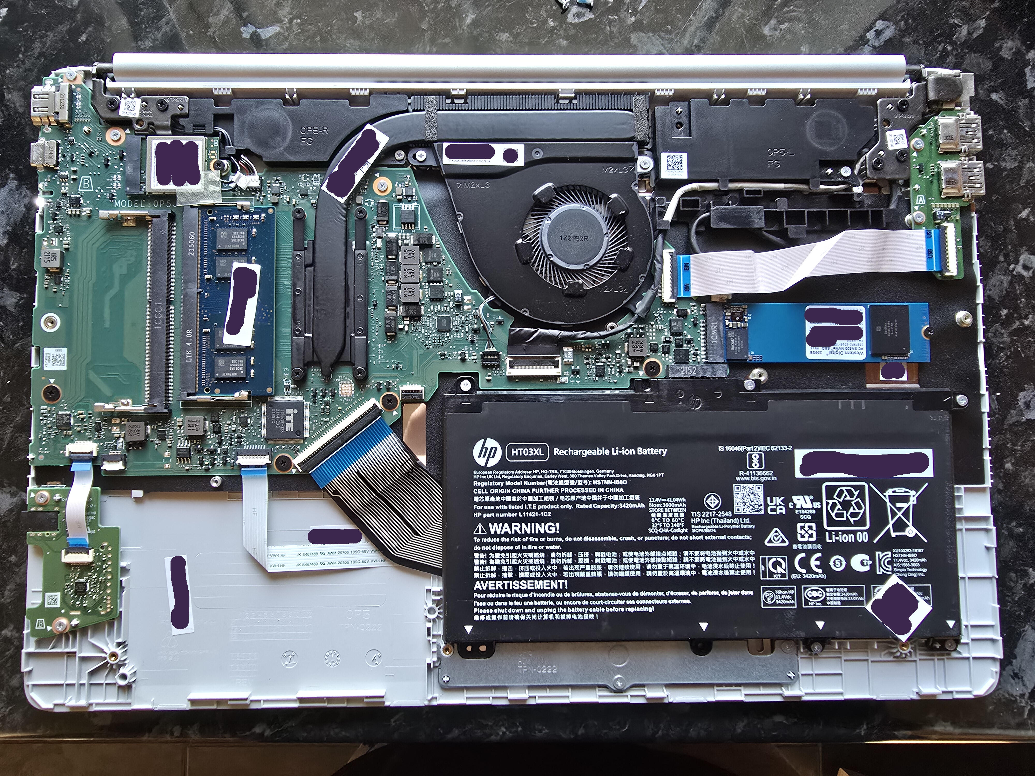
I removed the bottom panel screws, actually, it's not really a "panel". By the looks of it, the palm-rest is the "panel" here, since it sits recessed into what would normally be called the "bottom panel". First step in and my forehead already grows a vain at the sheer existence of this device. I have dealt with few laptops with similar design, but with those, you usually remove the palm-rest from the device. But not here, NO.
With the bottom pan... ahem, the bottom, removed, I could now start to piece the innards apart.
I disconnected every cable, ribbon or not, from the motherboard and kinda bent them away. Then unscrewed and disconnected any non-motherboard thingy. I then searched the entire motherboard for screws like an optically stunted grandpa reading today's newspaper. I missed one, but it was easy enough to spot once the motherboard wouldn't easily be lifted out.
Did you know displays were really flexible? I was shocked to find.
I tore away the display bezel after I got some grip with my fingernails (should I perhaps put them in the collection of tools that was used?), and found the display sitting in the middle of the top-lid, kinda menacingly, since I didn't see a single screw holding it in place, what the hell?
I removed the webcam PCB, WiFi/Bluetooth antennas and some kind of support-brackets I assume were there to keep the top-lid more stable in this ABS prison.
Looking around the display, I saw nothing holding it in place. So, I tried to just pull it from where it sat. Grabbing the top and bottom of the centre, then pulling. And pulling. And pulling some more. It bent so much it was giving folding phones a run for their money.
I'm joking a bit, so don't try this with any of your devices please.
It bent enough that I got a good look at the back of it and saw what was holding it in place; double sided tape, running parallel down on each side of the display. I didn't notice it before, but there was some of it protruding out the bottom. I'm assuming in order to get a little grip, and then pull, because this was the fancy pull-tab kind that you find behind batteries in flagship phones, oh là là.
Checking If Everything Survived
After a bit of heavyhandedness, I should probably check if everything vital survived.
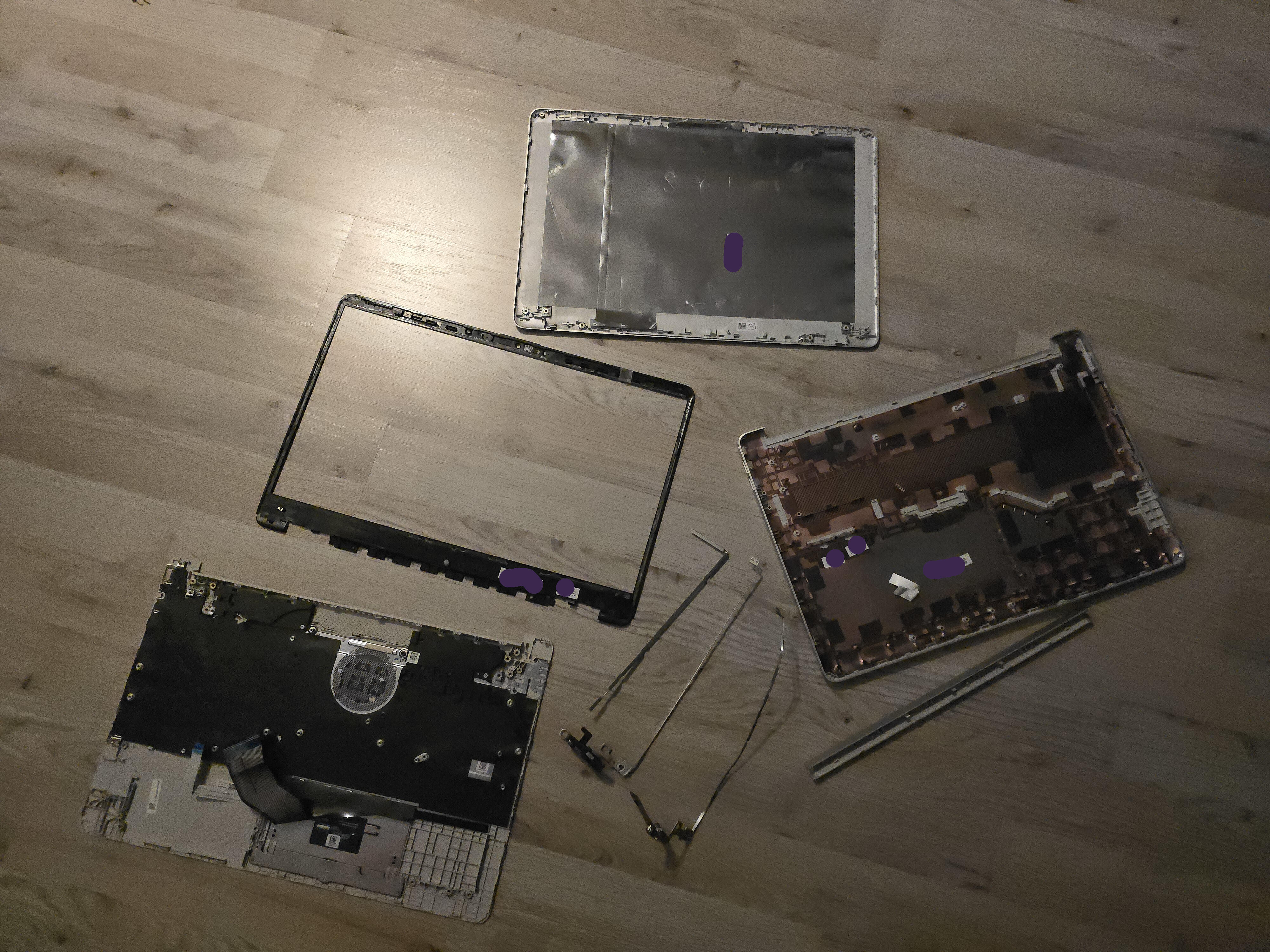
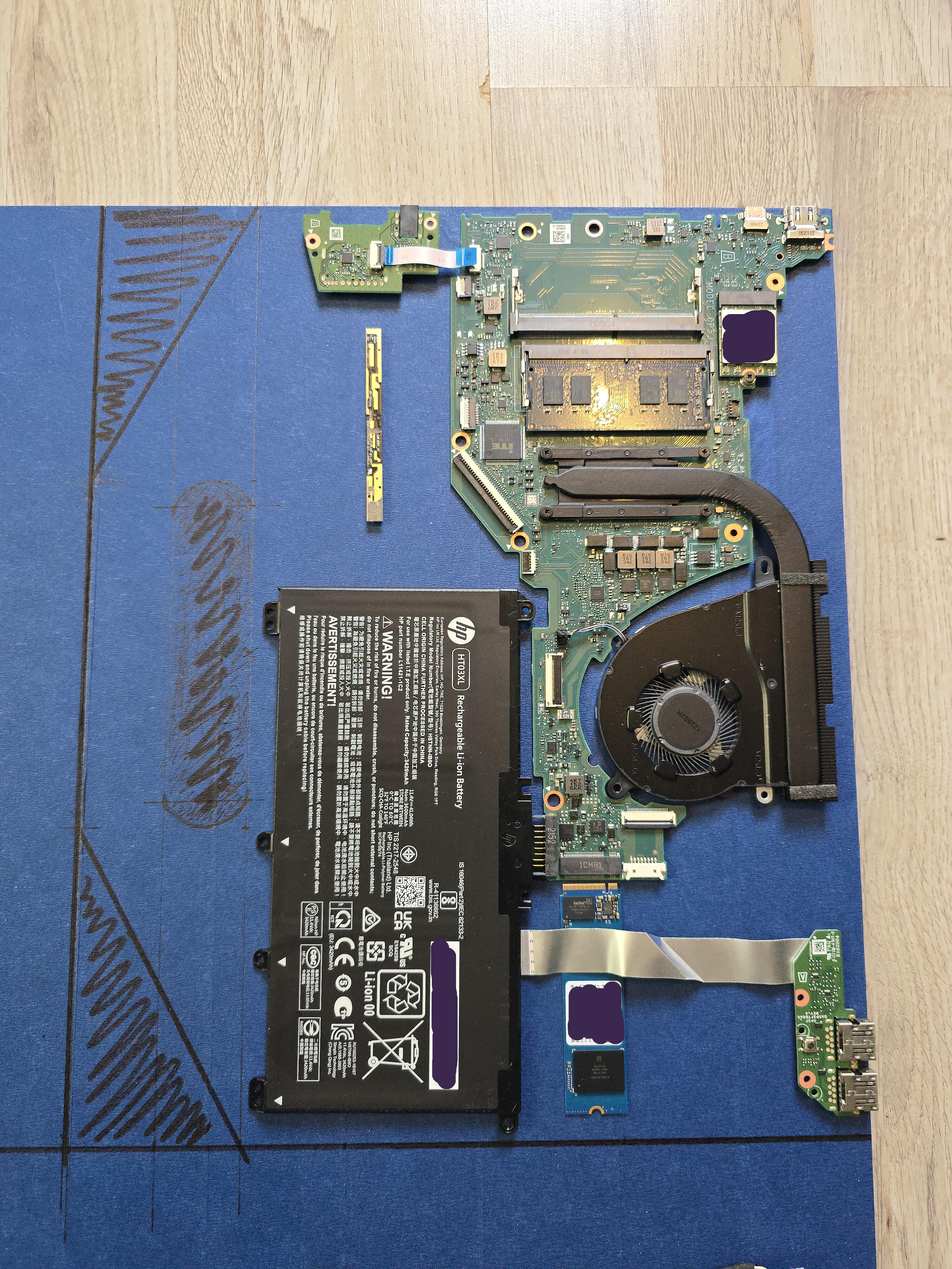
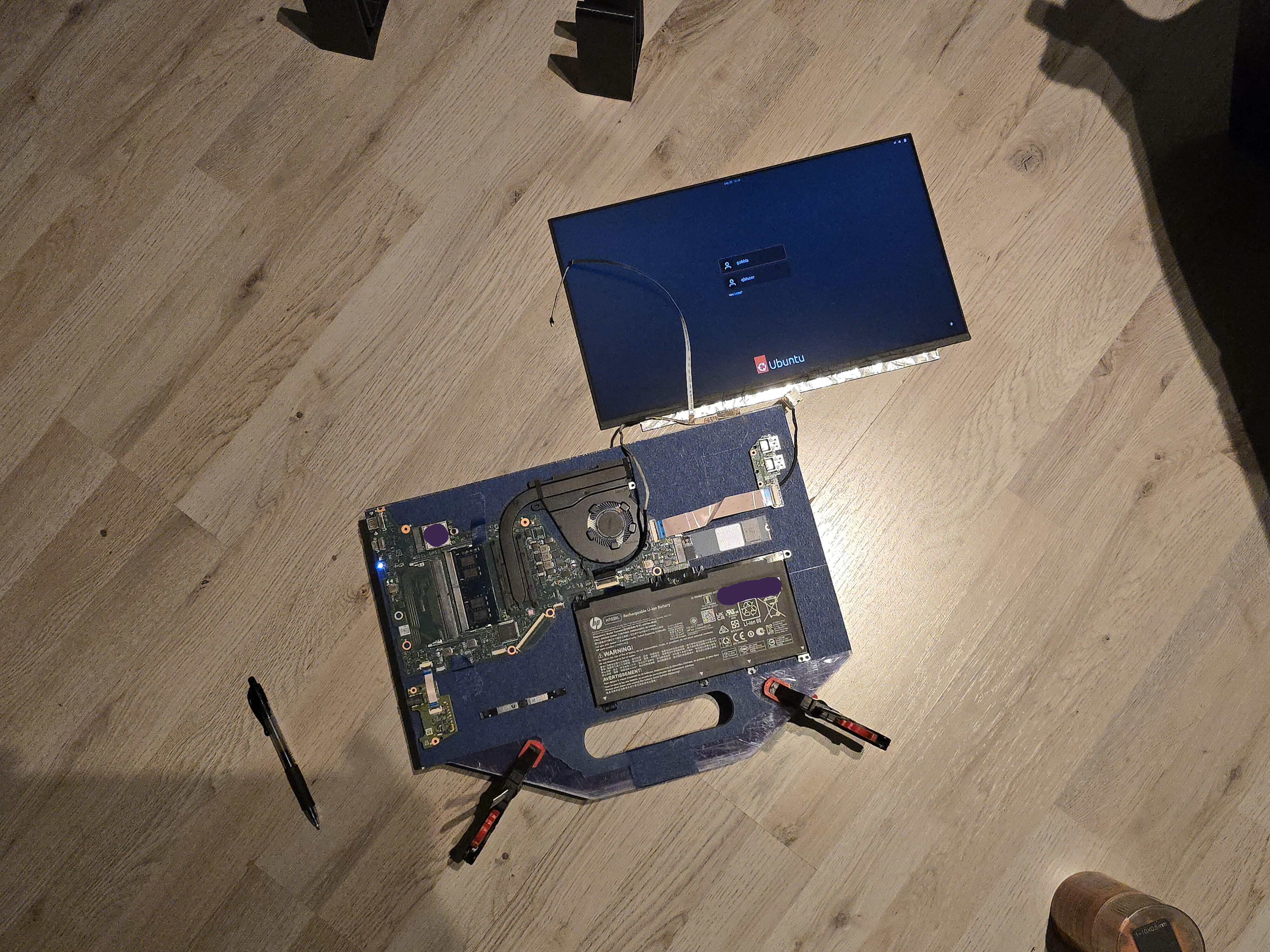
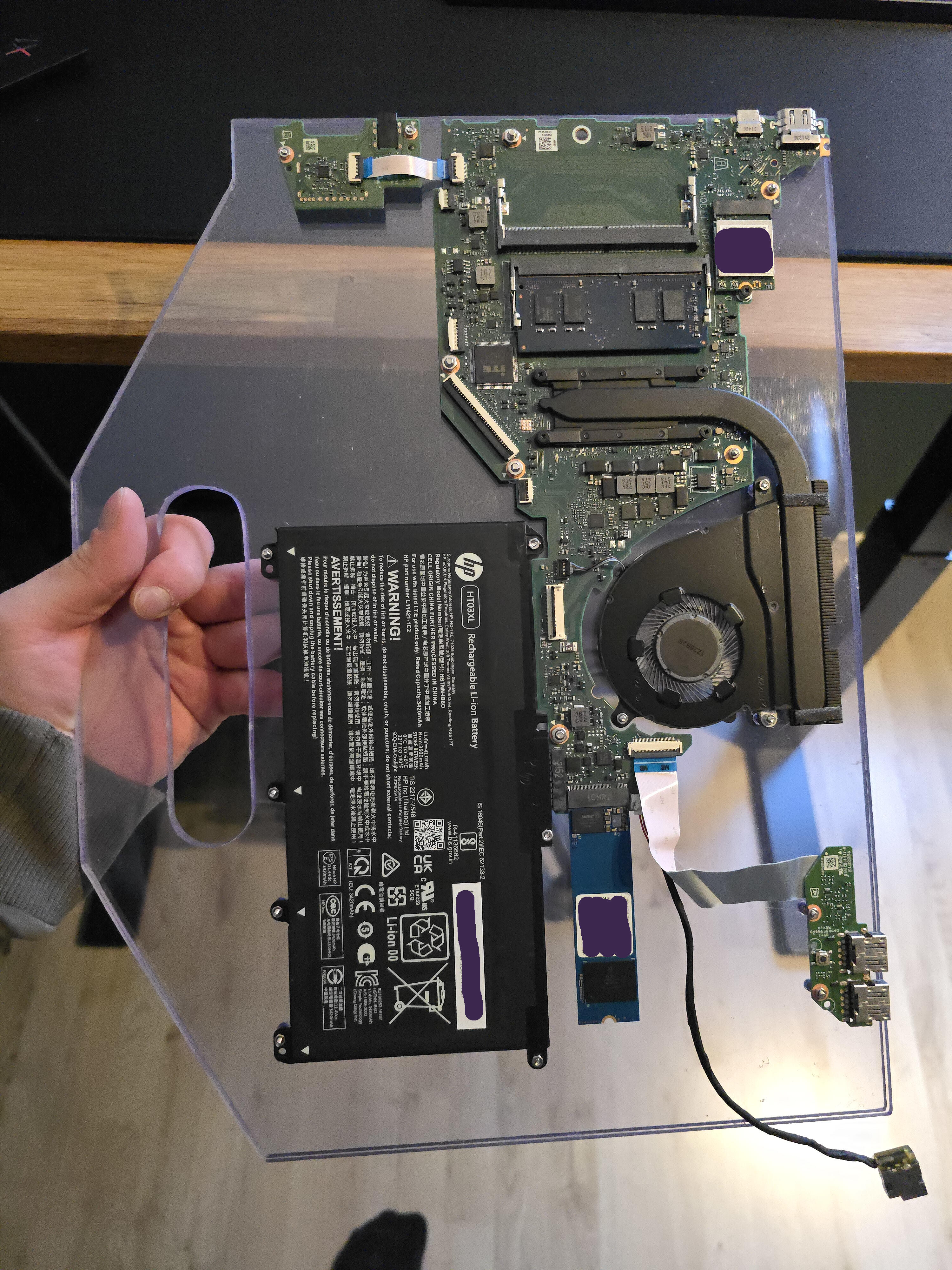
I laid out the important bits and pieces on the floor, connected it all, and pressed the power button.
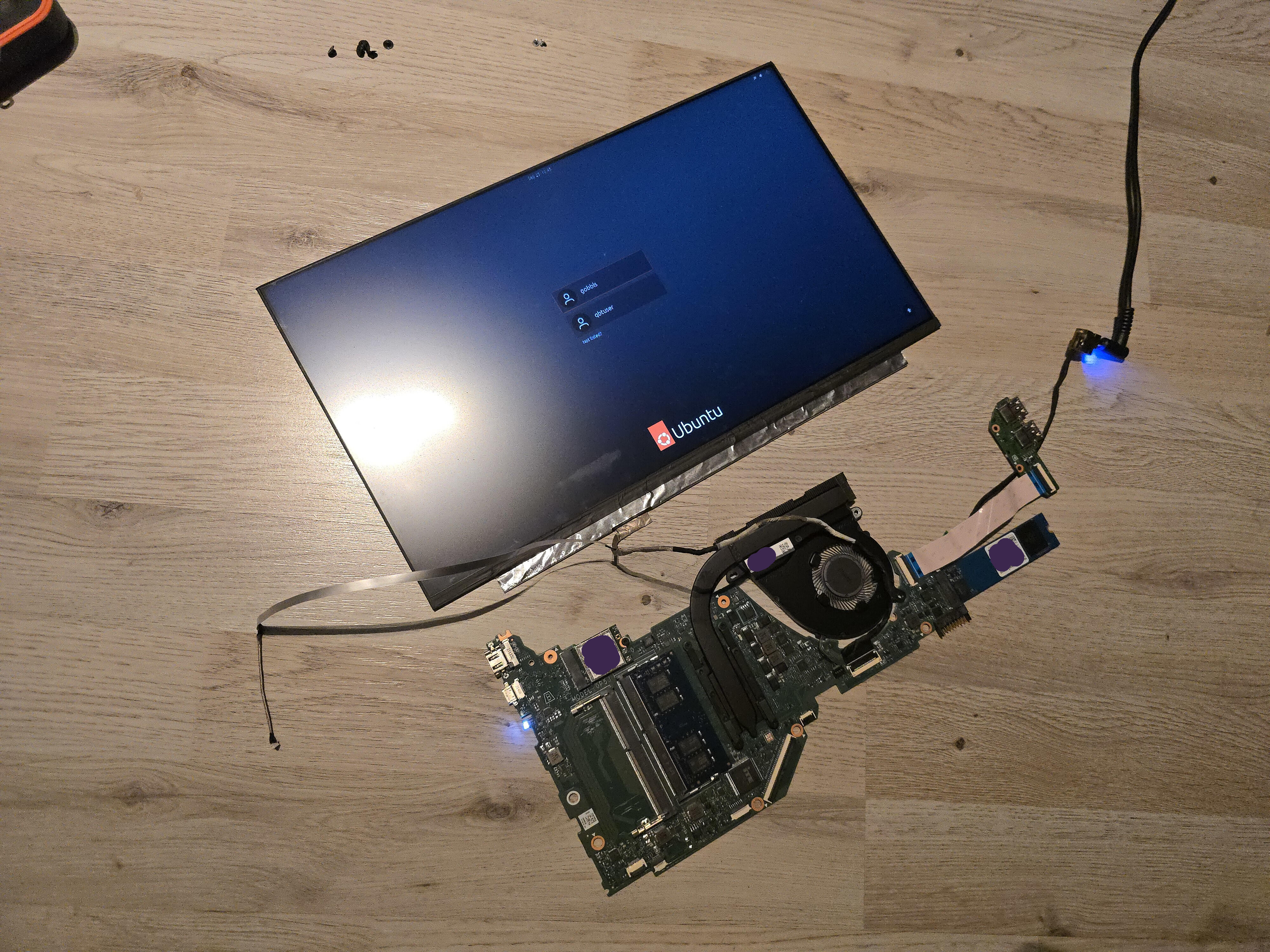
Hell yeah.
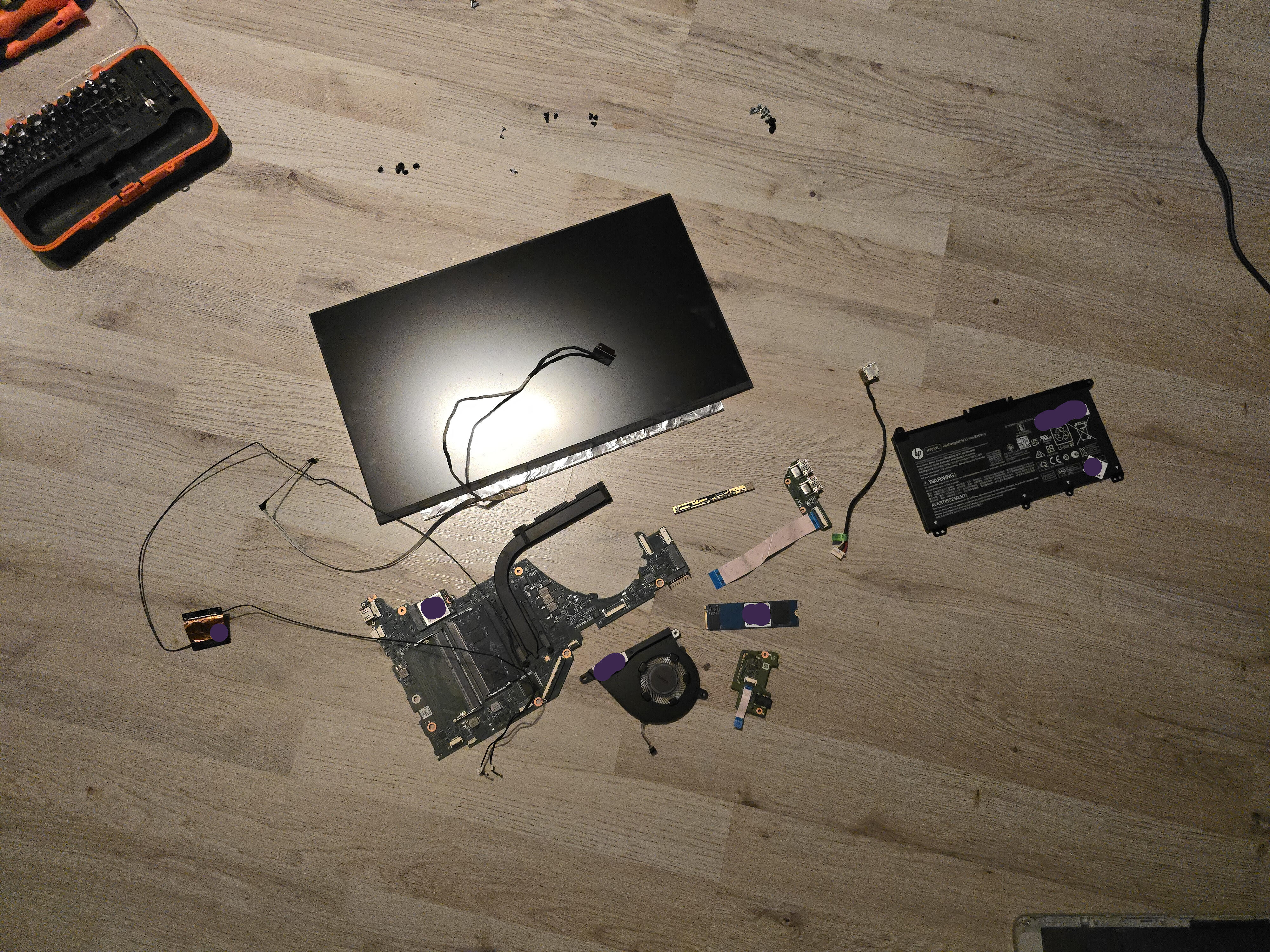
Here are all the pieces of the computer I'm left to work with. Except the antennas, I messed those up.
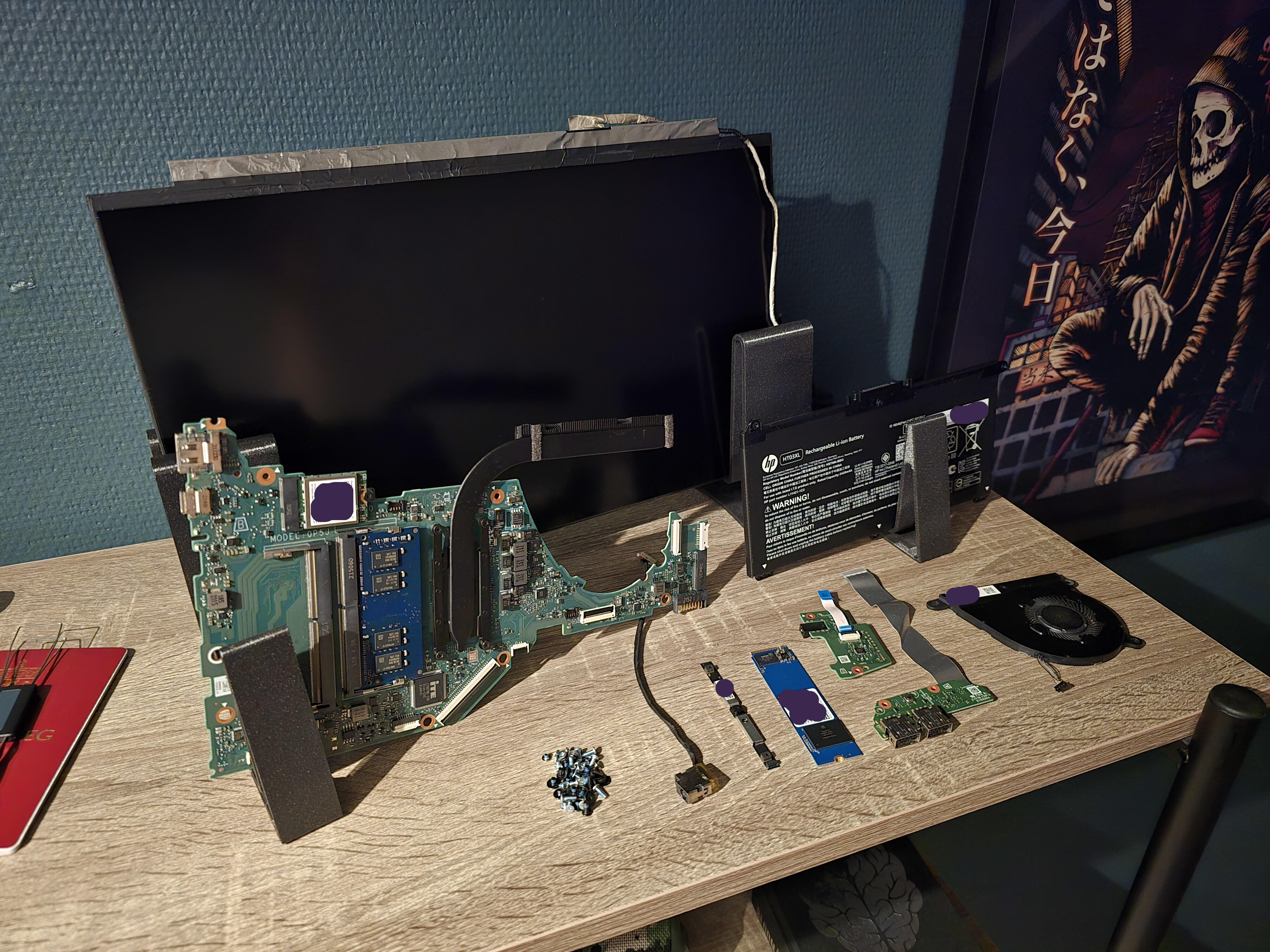
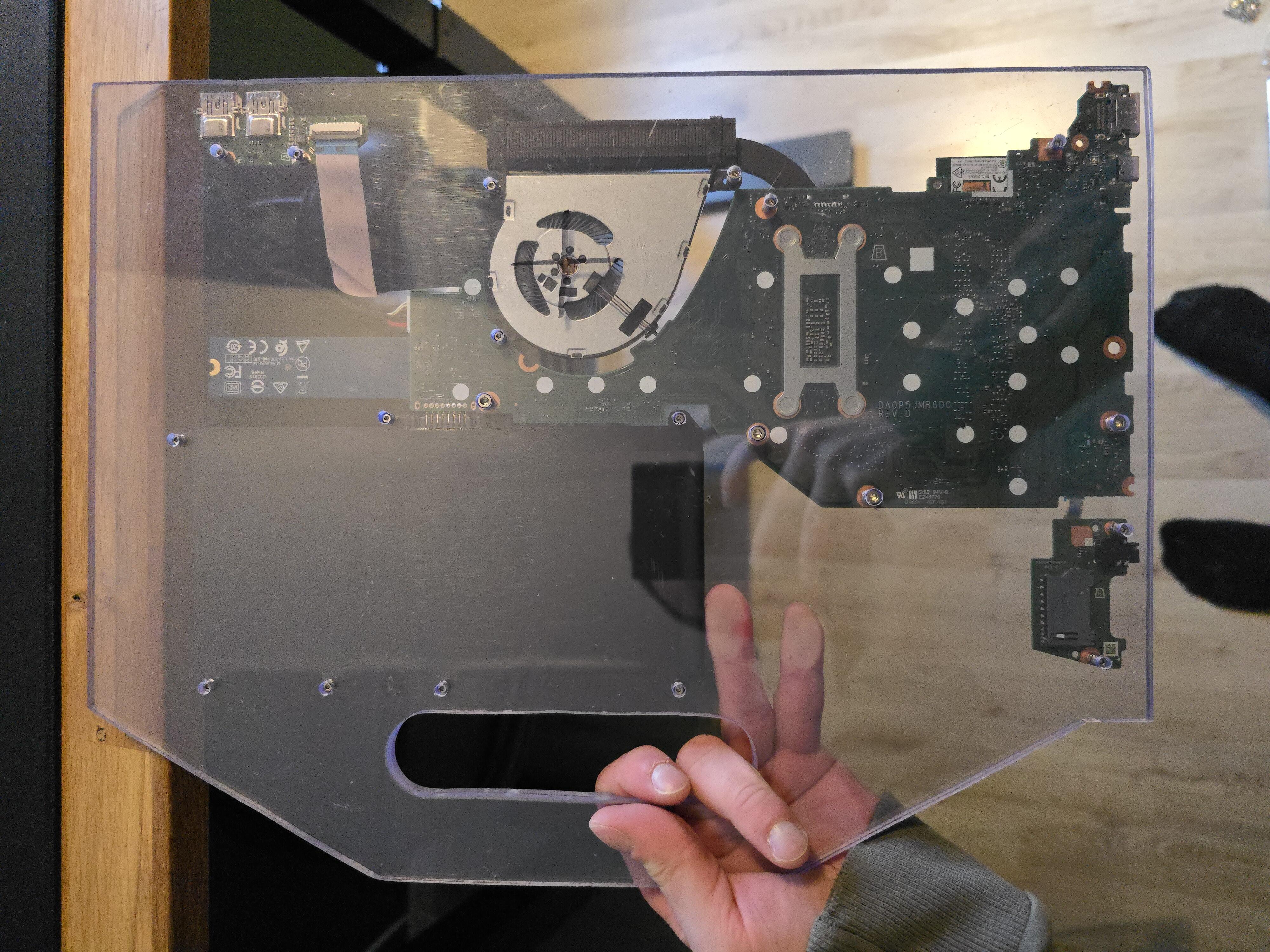
I put it all on top of a shelf while I was working on the chassis.
And here is the remains of the laptop, basically everything that made it shitty.
It is now solely up to me if it's shitty after the work is done. No pressure.
Chassis Time
Planning
I was at the gym doing leg-presses when I decided I wanted to commit to this project. I picked up my Samsung S24 Ultra and drew a sketch in the notes app with the stylus.
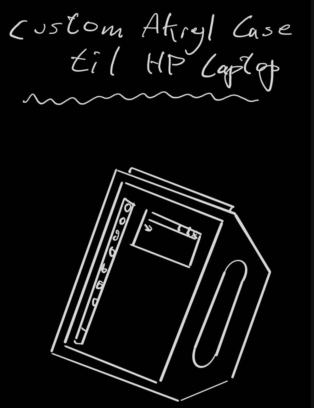
That's it, that's all I want.
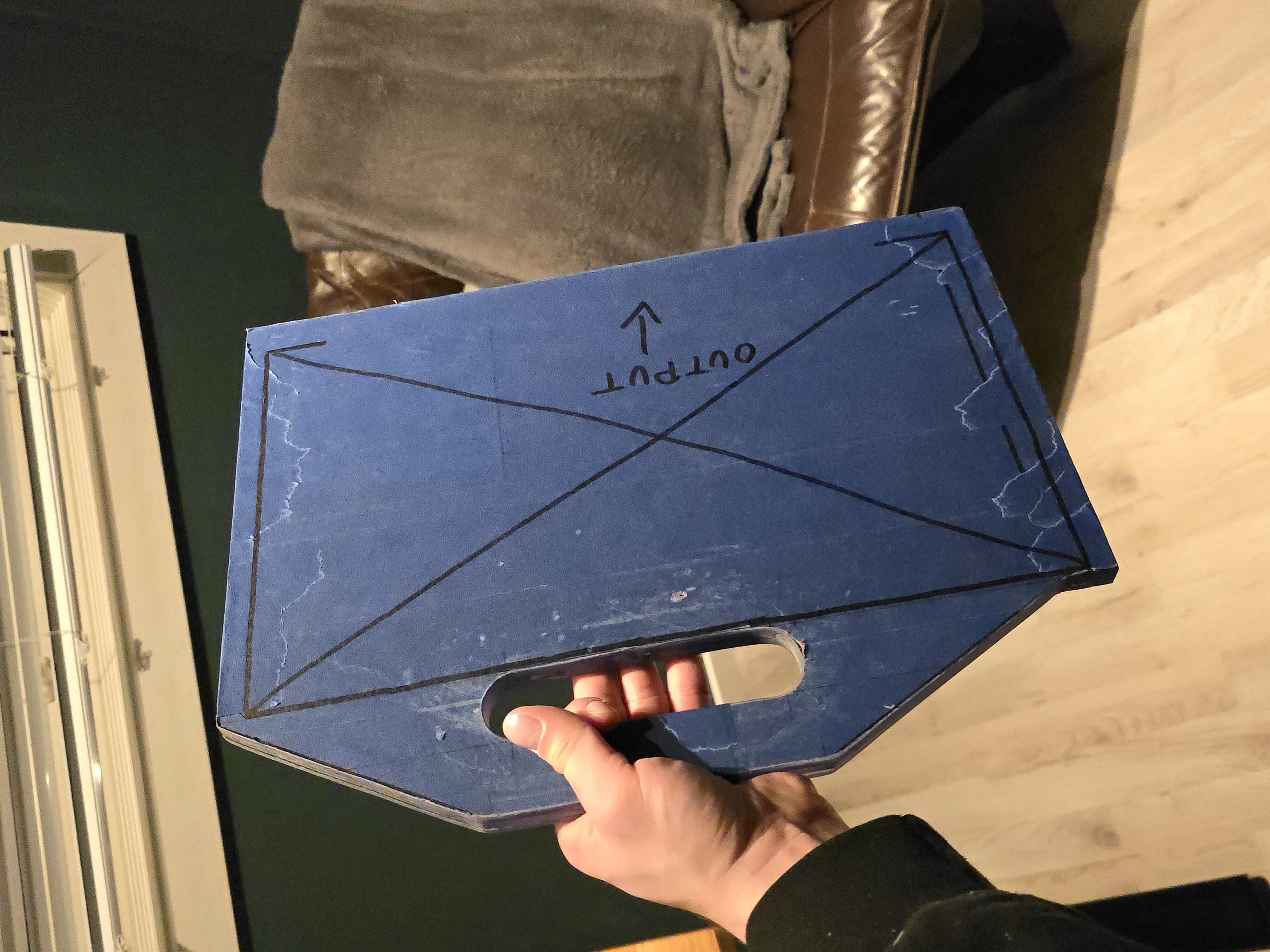
A vertical "tablet" with a handle cut from the frame, specifically not mounted to the frame. I feel like it was inspired from somewhere, but I'm not able to recall.
I had a feeling 4mm acrylic would not endure until the Heat Death of the Universe, so I added another layer to the plan, not only for the durability; when I decided on how the components would be mounted on the acrylic, a second layer of acrylic — with holes — would be great for covering the screw-heads when double-side-taping the display to the front plate.
This way, I could just add as many nuts and washers as needed onto the exposed threads of the screws to get a decent gap between the PCBs and acrylic as well as aligning the components for great stability and minimal stress on the PCBs.
Then a third layer of acrylic that would only be for strength and comfort of the handle. Cut in such a way that would not interfere with the components.
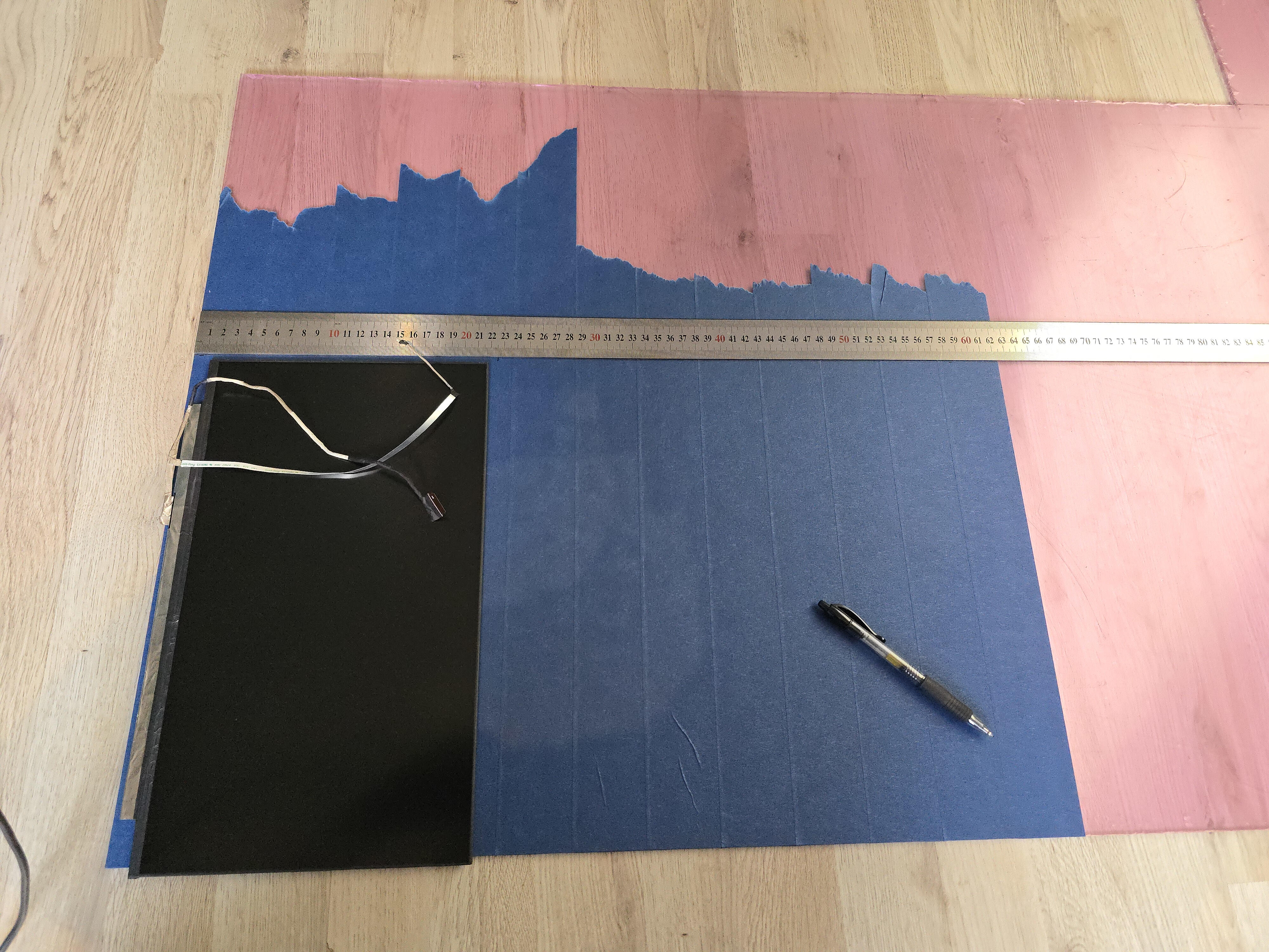
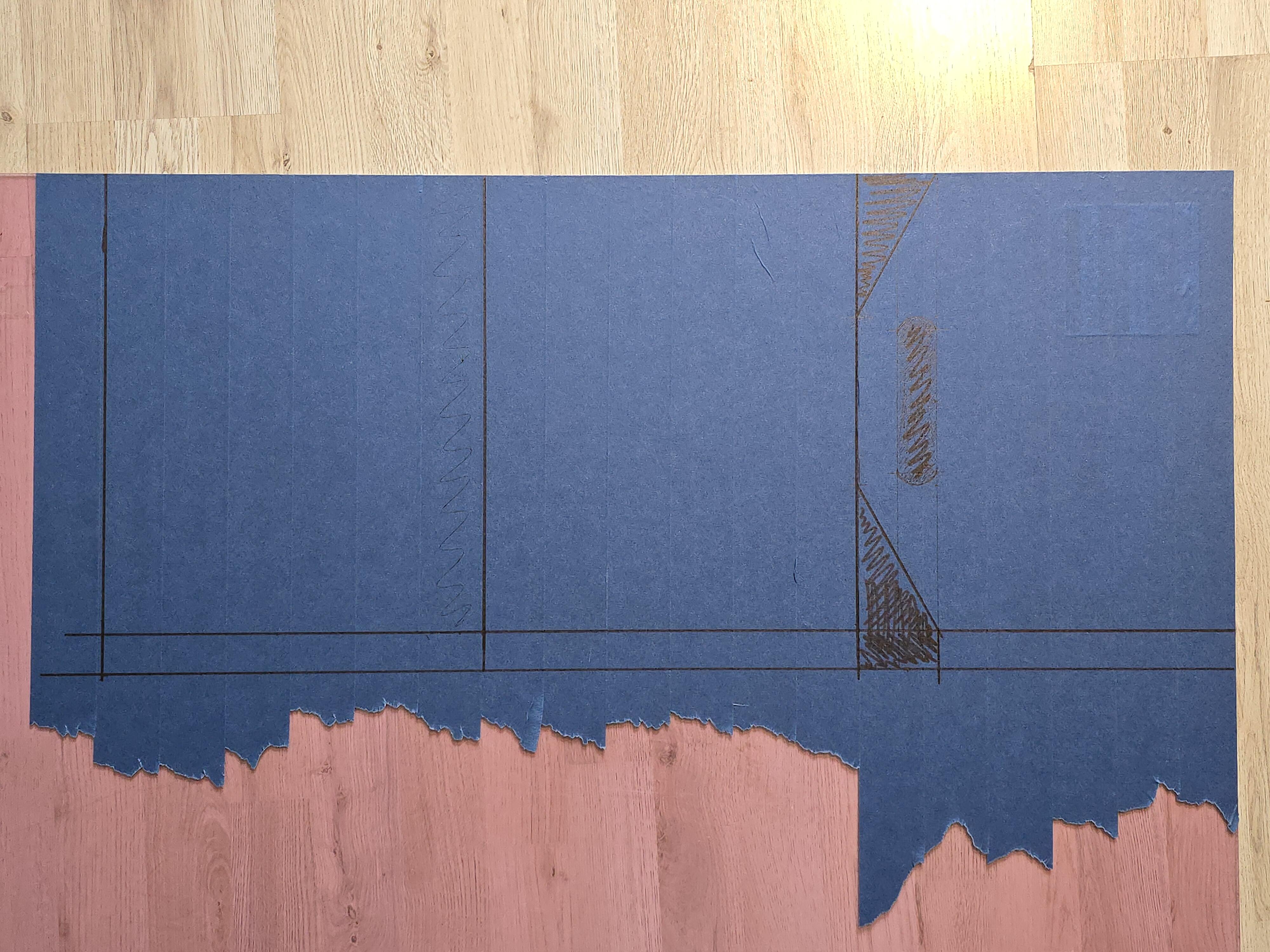
With this plan in mind, I brought in the acrylic from the garage, covered it in blue painters tape, laid out the components and started drawing along a metal ruler.
Just before getting ready to cut the layers, I remembered I would probably want some type of stand or holder to act like a monitor-arm to keep it upright. And that holder would probably have a bit of a "chin" to avoid a device from slipping off. So I decided last minute to add a couple of centimetres at the bottom, so that the display would not be covered by or touching the "chin" in such a scenario.
I didn't change the angle of the cuts for the handle to adjust for these changes, but in hindsight I wish I did.
Cutting
I went back to the garage with the acrylic and put two crates on the ground outside, put the acrylic on top of the crates with the line to be cut placed in the middle between them. And put a heavy toolbox on top to keep it from sliding around during cutting.
The sawblade I used for the jigsaw was apparently made for sheet metal, but cut acrylic really cleanly. High speed on the blade — with the machine going slow and steady — is key.
I did a rather rough cut first, just to get the three squares out the sheet for better handling. I then sandwiched the three plates, and held them together with a couple of clamps. I then ran the jigsaw around, moving the clamps one at a time, cleaning up the edges. This went surprisingly well.
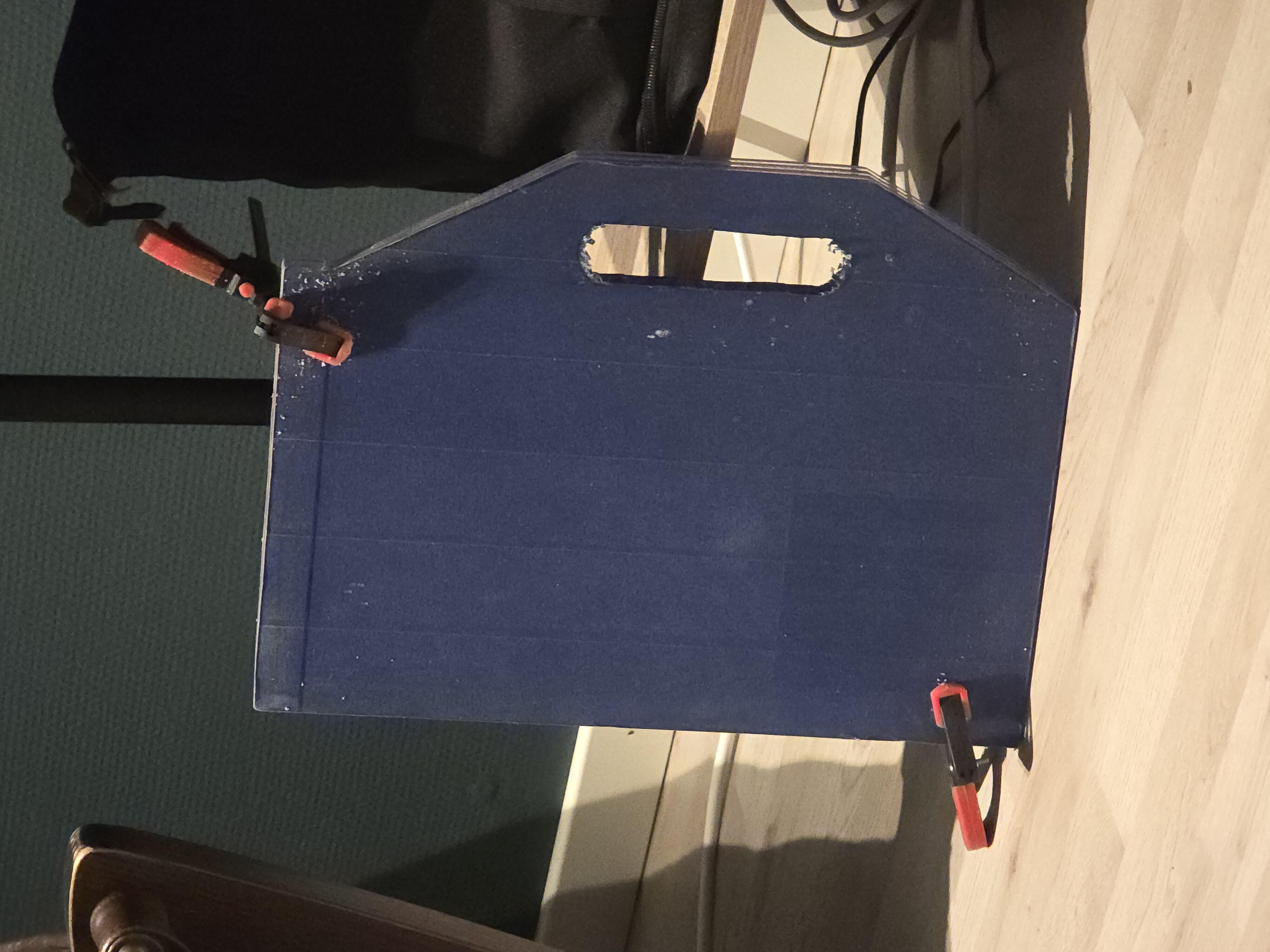
With the cleaned up edges, I then moved on to the handle.
It took some time and was a bit PIA. I used a drill with a bit big enough to fit the jigsaw, making holes about every 3cm to make the jigsaw-work easier. When the middle part finally fell out, I then cleaned up the edges like I did on the outside, by running the jigsaw around until I met the planned line.
It was getting late, so I waited to do the sanding work till the next day.
Sanding the Edges
With a respirator mask on (because sanding plastic is no joke), I slapped on a 120 grit sandpaper sheet and went to town. Like with the jigsaw, I went around and moved the clamps as needed, which continued to work as a charm. I was a bit concerned that the plates would shift a bit, causing unevenness, but it worked out as planned every time I checked for misalignment.
I'm still a bit shocked that this worked out as well as it did. Usually, at this point in a craft project, I have already fucked up four times and got blood everywhere for some reason.
Not this time though.
Since we are still in "Sanding the Edges", does the inside of the handle count as an "edge"? Shurely.
I was offered to borrow a Dremel from Mr. Colleague for this exact scenario. My father had a Dremel I could borrow, but Mr. Colleague's Dremel had an attachment[2] that let you slide the Dremel steadily on the surface while the bit did its job sanding away at the edge.
With plenty of patience — and none left to spare in the end — I Dremeled' away the sharp bits and got a smooth handle in the end. I will be using some loose, folded sheets of sandpaper later to round the edges for optimal comfort.
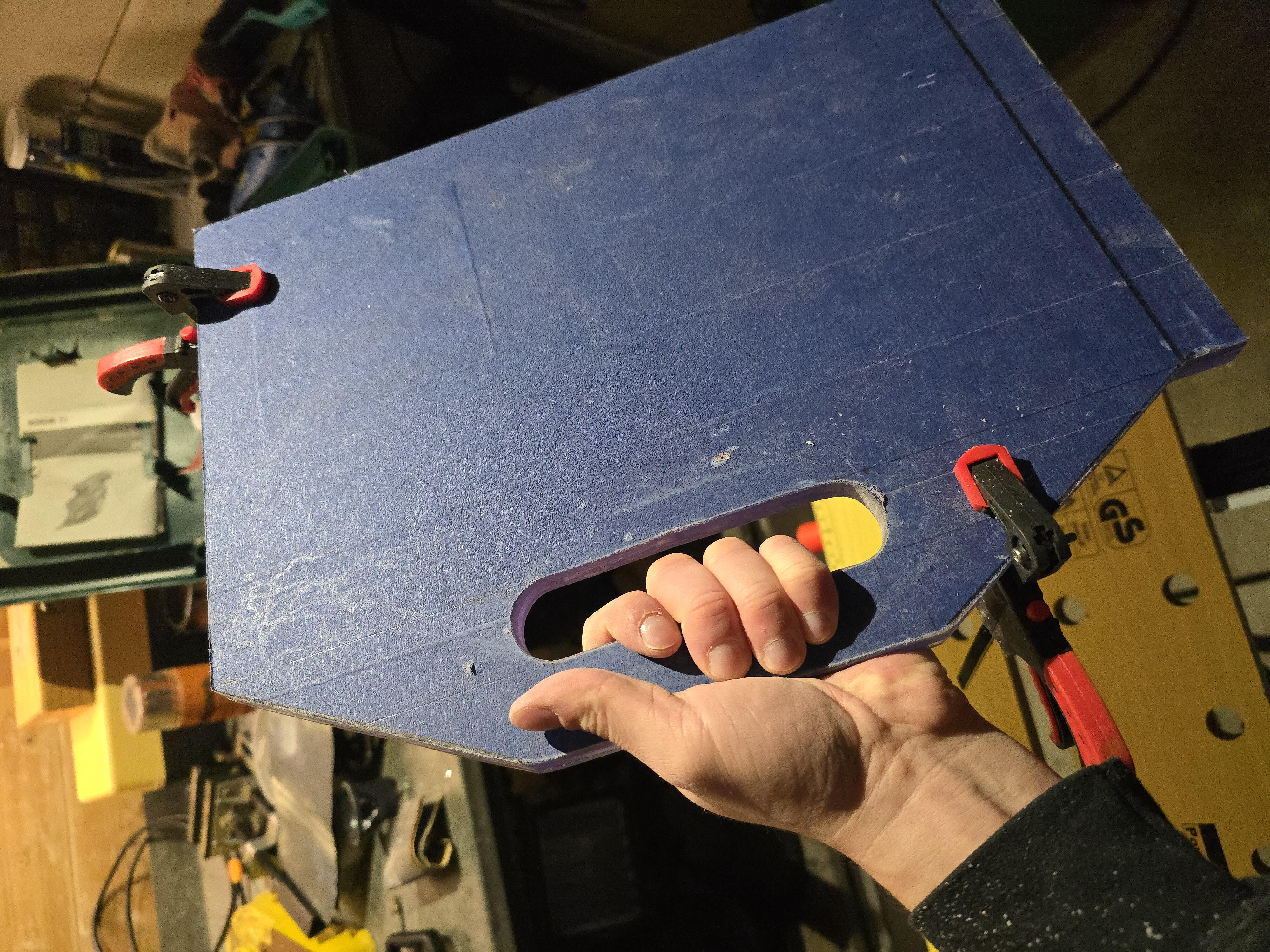
It feels really good in my hand. The weight is perfect and screams "durability". Acrylic shatters if it gets mishandled
correctly incorrectly (?), but with two layers behind the display and a third for the handle, I'm not worried whatsoever.
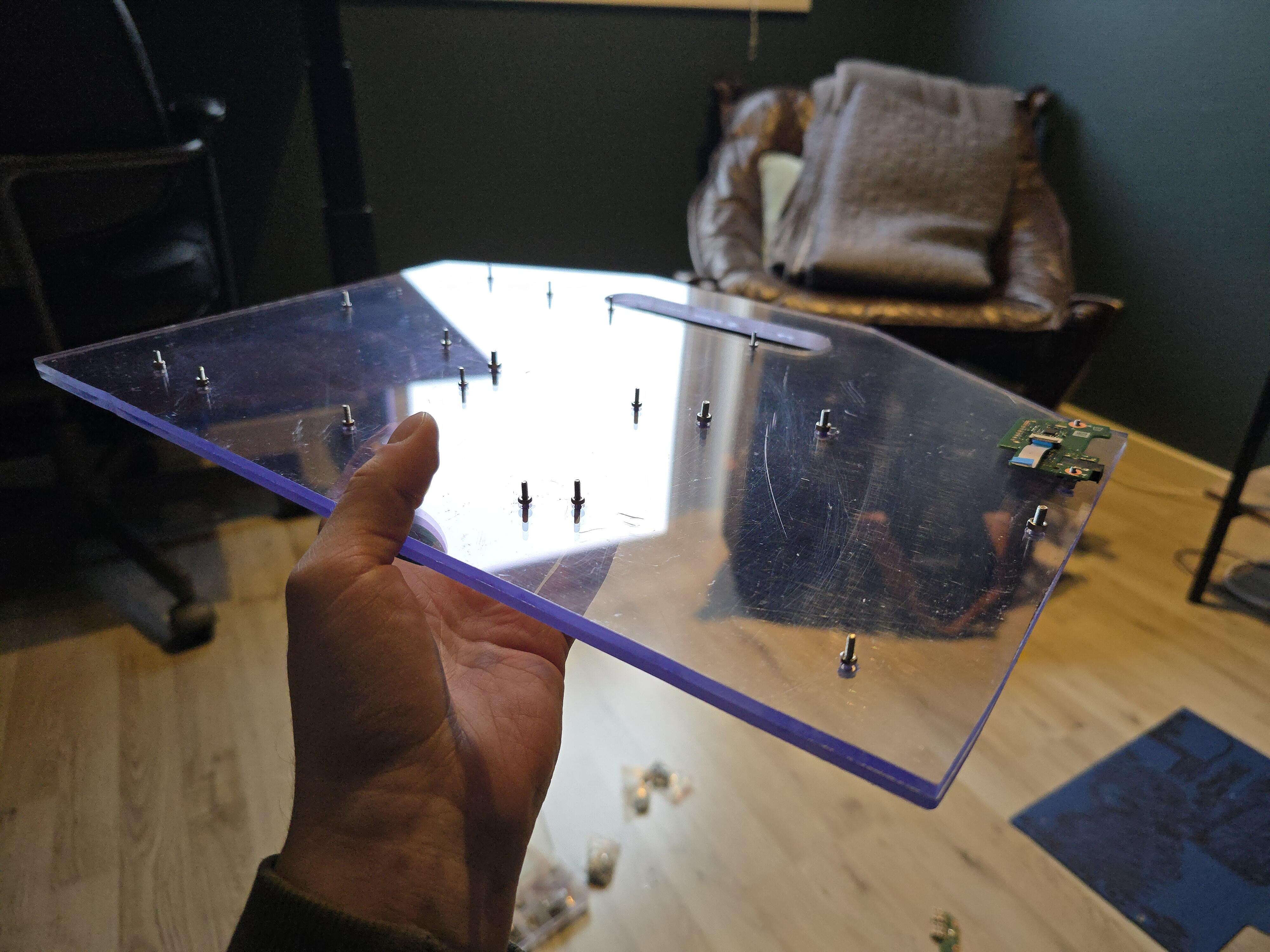
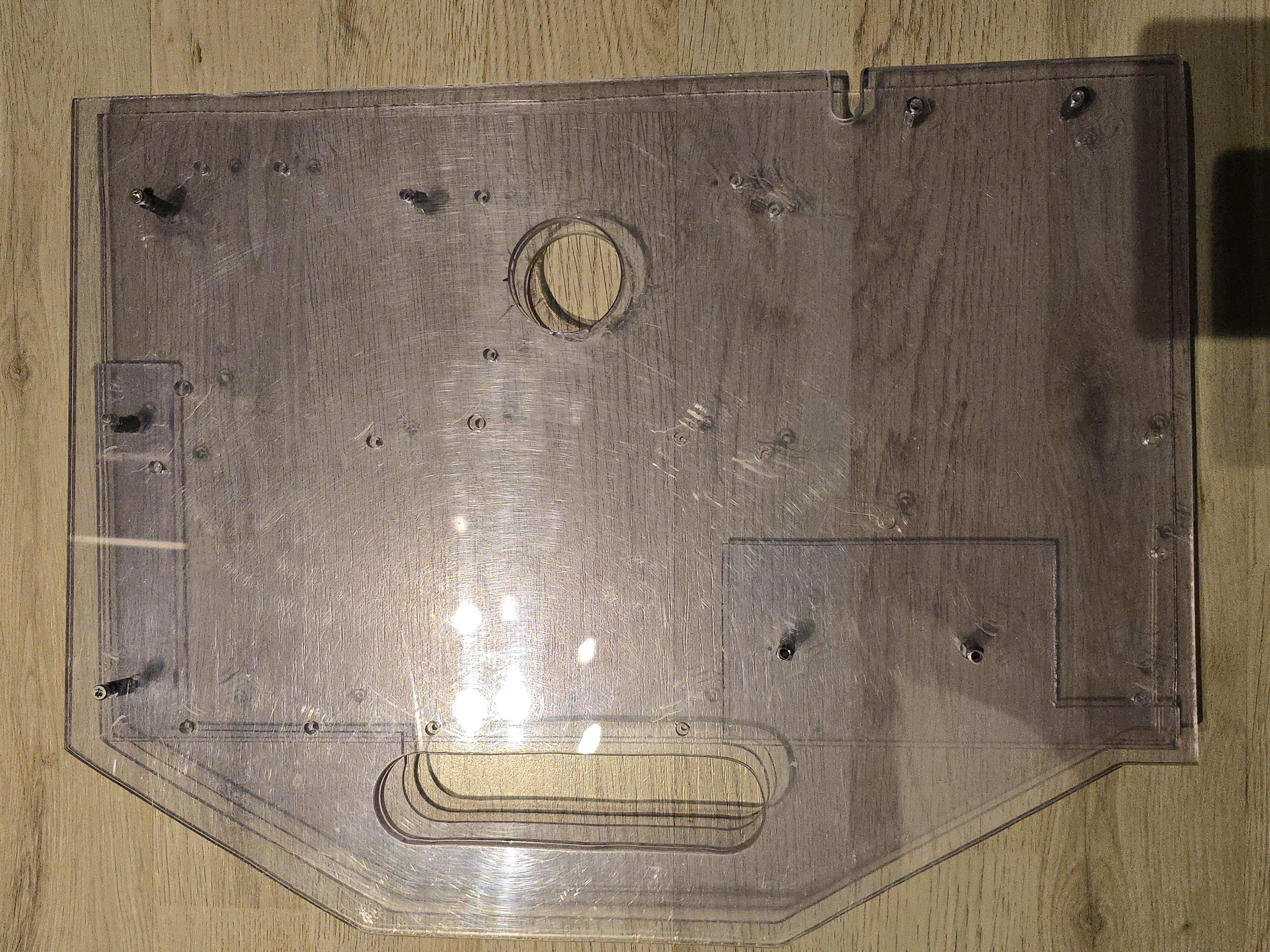
Drilling Holes for Mounting the Components
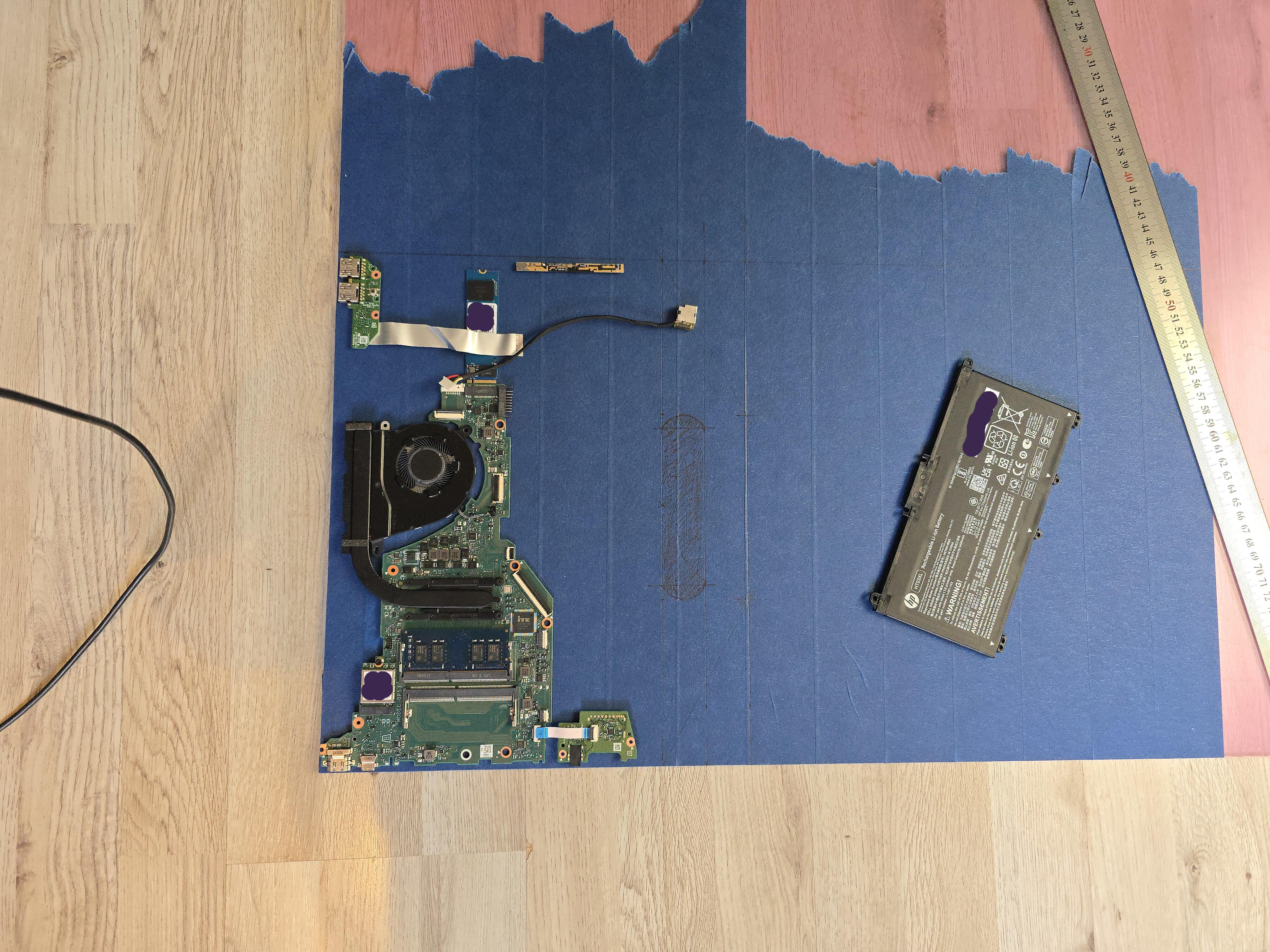
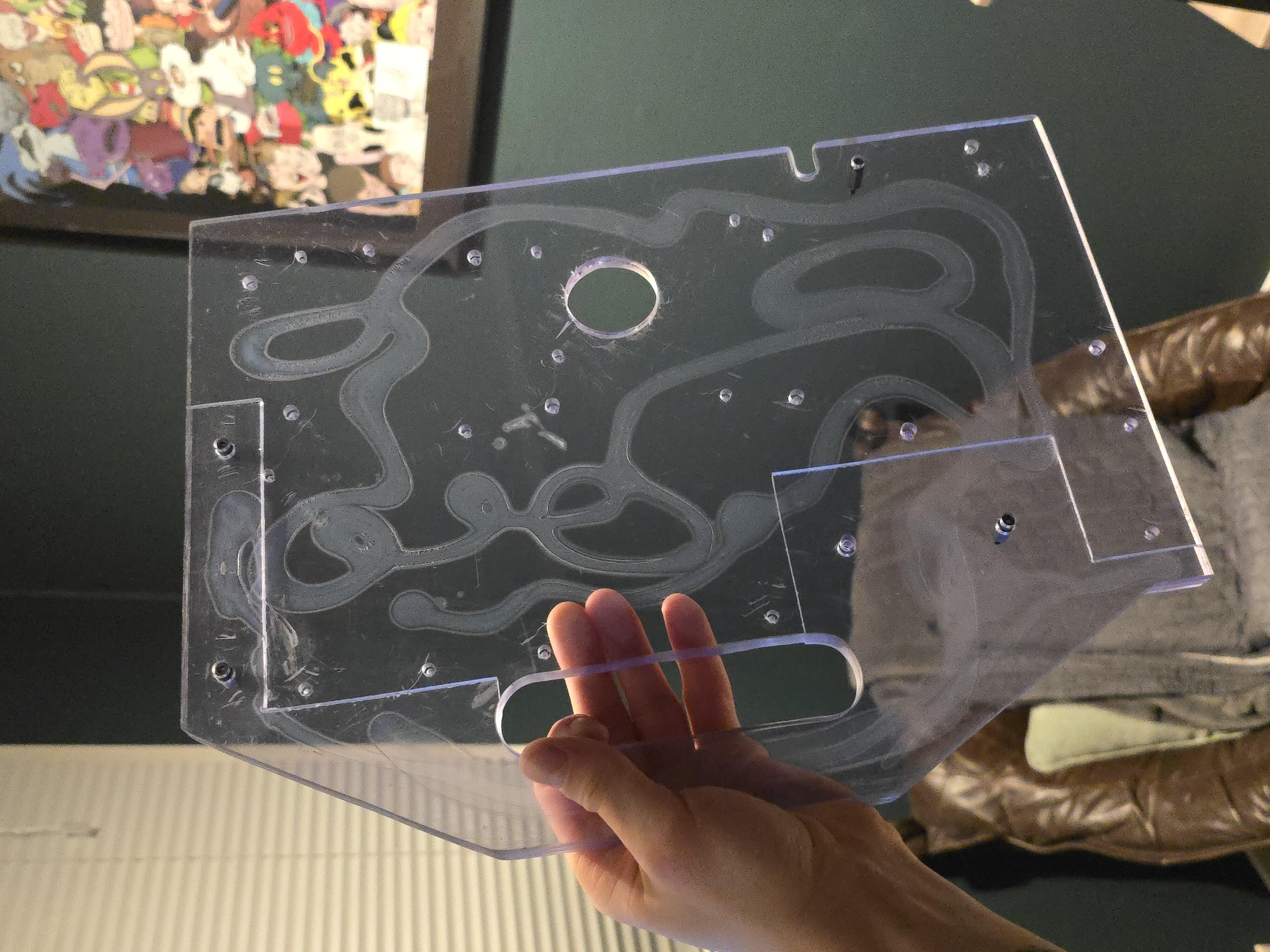
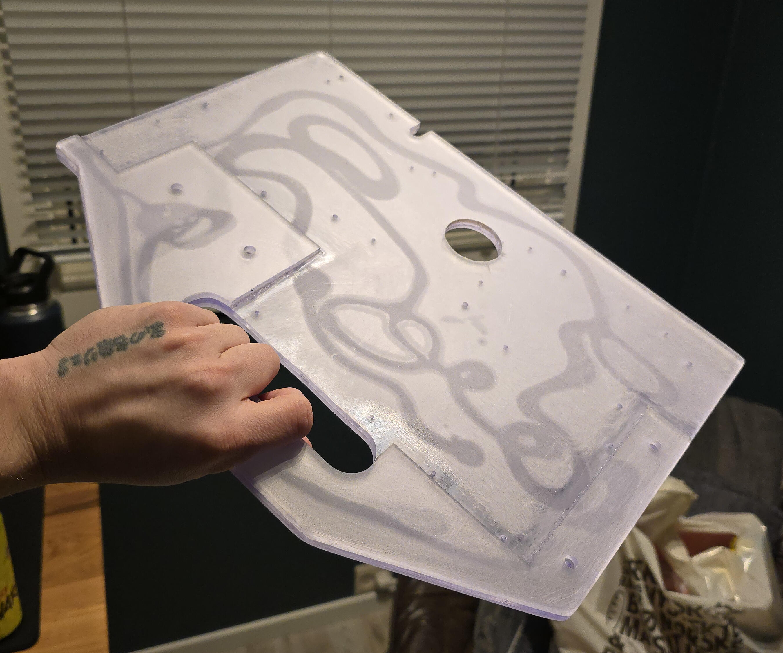
One more time I laid out the components onto — what is now — the final, general shape the device will take and started to draw around the components and making dots with the pen where the screws will go through.
I used a drill press near the edges, and a regular drill near the middle, to drill the same small holes through all the plates, then making the holes larger bit-by-bit to avoid cracking the acrylic. I'm being extra careful at this point.
When all the holes reached the size of the screws that would go through them, either M2 or M3, I could now separate the plates, since they could easily be re-aligned with all those holes.
Now was also the time to remove the painters tape and the thin, plastic film on each side of the plates.
The last holes to widen was on the plate where the display would be mounted, and where the heads of the screws will sit recessed into the plate.
Just as planned.
Now, before continuing with the hole saw and create some airflow for the fan, it would be neat to know if every screw is aligned nicely with their respective component.
Damn right they were!
Although I waited to drill the hole for the M2 screw holding the SSD in place, since I had a feeling it would be misaligned if I tried to drill that hole without actually knowing where it would sit precisely on the plate.
I went on to drill that hole with complete confidence.
Cutting Some More!
Now, while holding and getting a feel for the device, the back — with all the sensitive components — feels really exposed. "Naked", even.
I should perhaps have cut a back-panel while I was cutting the other squares, but I had no problem getting out the jigsaw once more and start cutting again. Took about fifteen minutes. And luckily enough, I had just enough acrylic to get another square of proper size.
I also cut room for the components on the third layer, since they will be on the same layer. This was a bit more of a diligent job, as I wanted it be able to take up some room in the "body" of the device in order to assist with the rigidity of the handle. The device is getting rather heavy, and some more support for the handle won't hurt. Although in the end, I don't think it mattered that much.
I neglected to take more pictures during this process, do forgive me.
Checking the Fit of the Layers
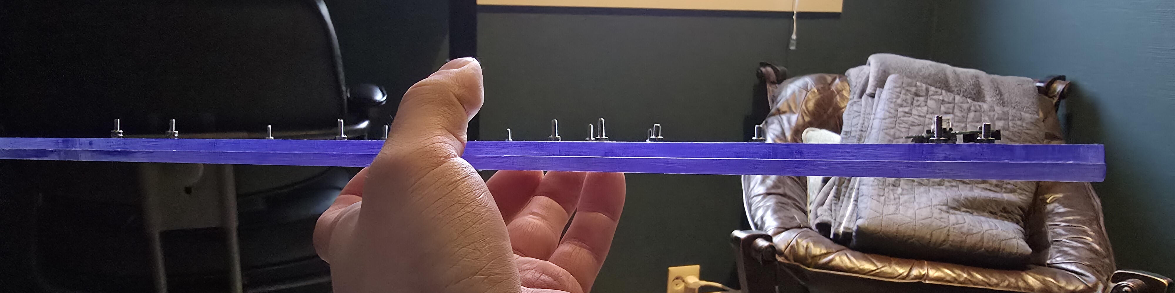
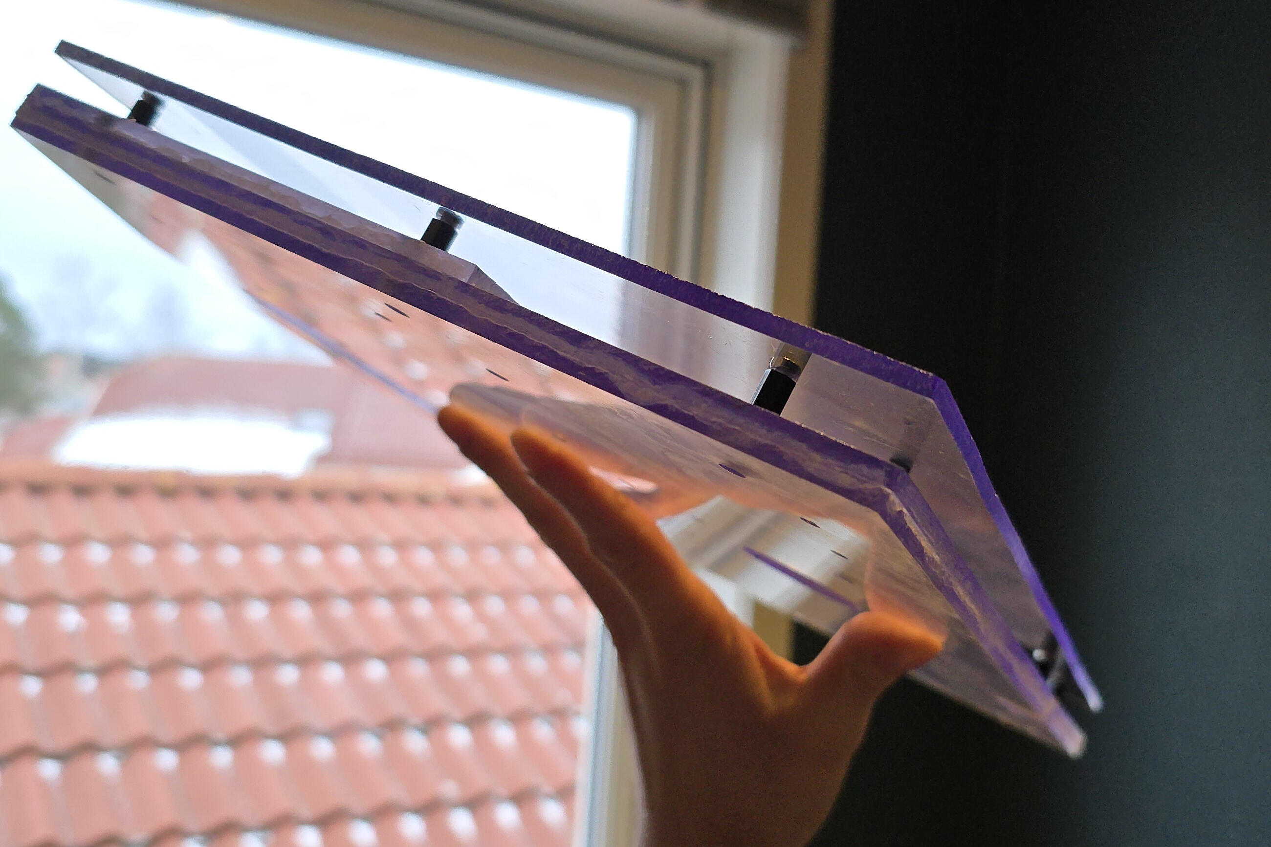
— After drilling some more holes for installing the standoffs (female-female), and even wider holes in the handle-layer for the standoffs to sit recessed inside (to avoid having to use different-length standoffs') —
I sandwiched the layers, making a proper PBJ (Plastic Bourne Junk), and roughly inspected if everything would sit together nicely.
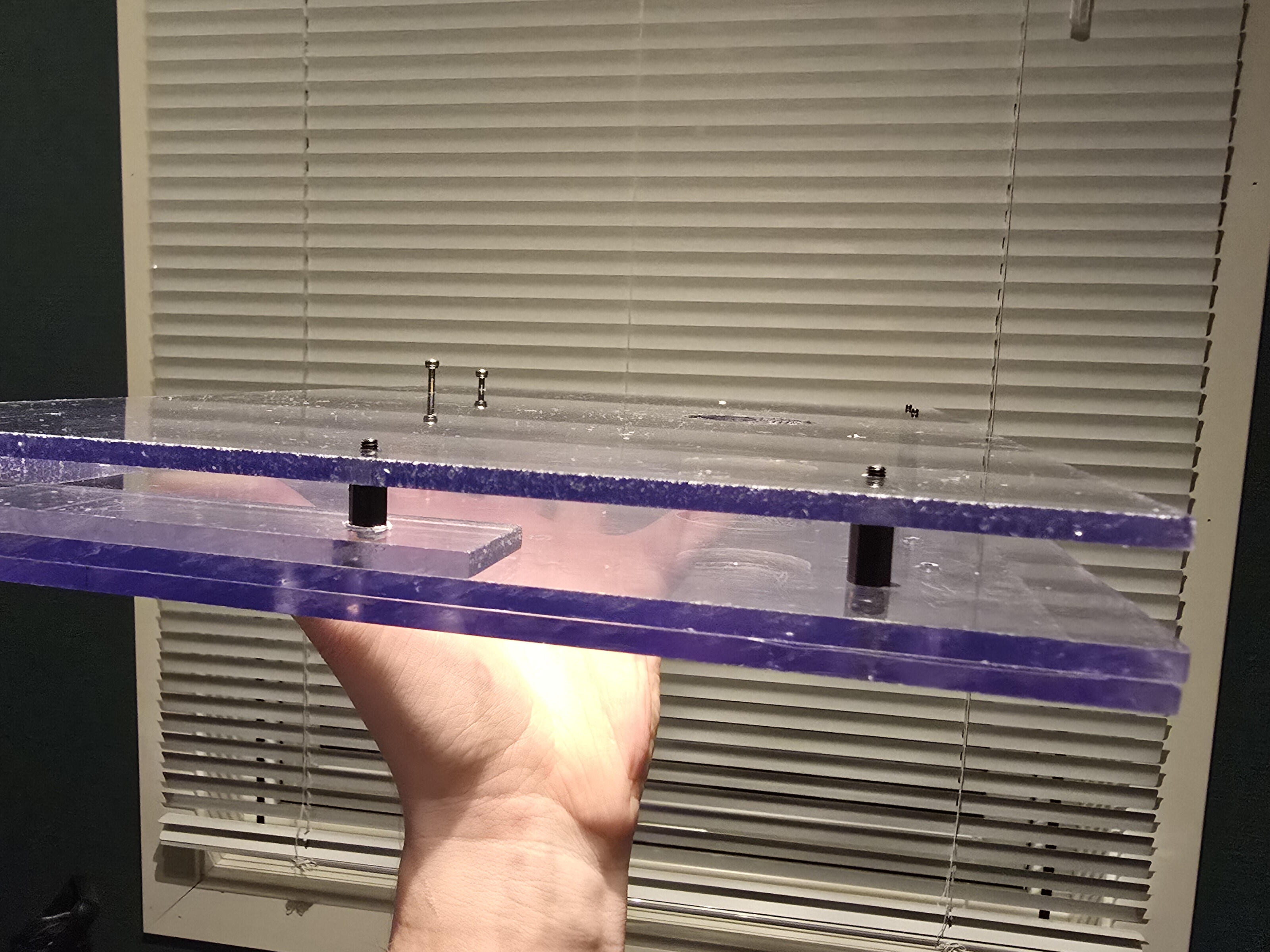
So far, so good.
HOW DID THAT HOLE GET THERE?
Hole saw. You do the math.
BUT THERE IS A CUT-OUT ON THE SIDE AS WELL!
Alright alright.
After seeing how the display would sit on the device, I noticed the cable really didn't have a place to go other than wrap around the chassis. And that would look real bad. So I sandwiched the two layers the display would be sitting on and jigsaw'ed out a little room for the cable to rest in and sanded it down a bit.
And that hole?
Blow hole.
Kinda. It's for the fan of course. The components already have all the air they need without it. But it was part of the original design. The original design involved painting the chassis, and I figured the Blow Hole would be a cool feature if the surroundings were painted. I still think so.
It was a real bitch to cut though. I sandwiched the two display-layers and the back-plate and thought the hole saw would make light work of the acrylic. But man, acrylic got hands.
I went too fast and the acrylic melted around the saw, getting a real grip on it. I was barely through the first layer when it happened. I disconnected the bit from the drill and started hammering on it. While disconnecting the bit, the plastic had hardened again and sat around the circular blade like Epoxy Putty.
Remember the "Tools Used" section?
The patience of a saint
- was not a joke, just a little.
I wiggled the hole saw around for a while, slowly loosening the grip, and using a screwdriver to push away the plastic from inside the hole saw (there are vent-holes around the saw, I went inside with the screwdriver and pushed the plastic away from the inside). I finally broke away from the plastic and sanded away the chunks of hardened plastic and got to work again, with a bit more patience.
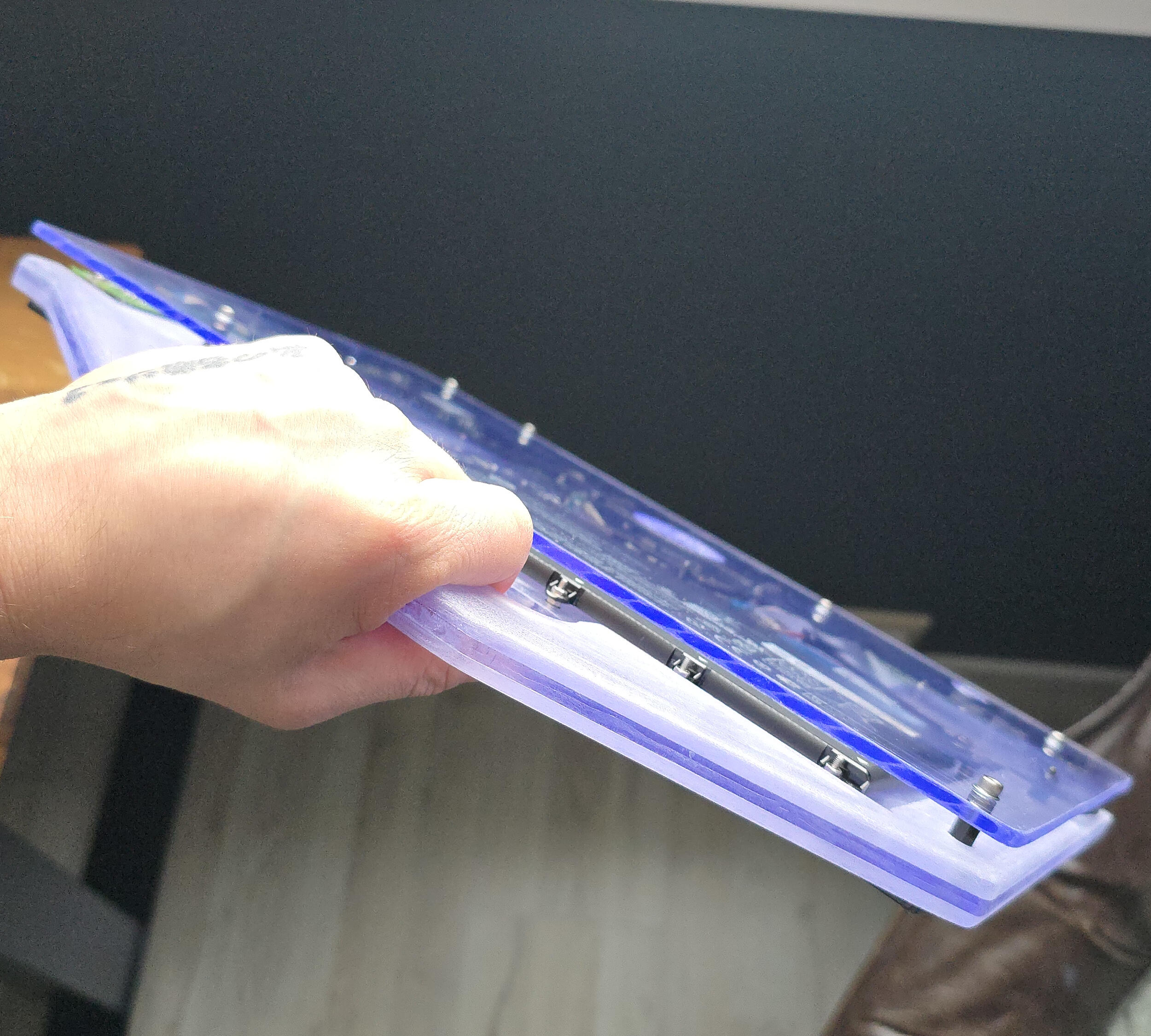
Gluing the Layers Together
The only layer the components are actually installed onto is the middle layer of the three-layer sandwich. That would mean nothing is holding onto the grip-only-layer, or the layer the display would be mounted onto.
So I got myself some glue meant for this kind of plastic. I first tested on a couple of junk acrylic pieces to make sure it would do the job. While testing the strenght of the glue, trying to break the glued pieces apart actually broke the acrylic first. Good enough.
I washed the layers in the sink with some soap and dried them off.
I laid out the display-layer and component-layer first, and let the glue flow. After getting a little bit of glue everywhere it mattered, I aligned the layers with some screws and pressed them together. The glue package advertised that it was ready in 60 seconds, so I waited only so long before I aligned the handle-layer and glued that on as well.
I put some stuff on top of the layers for weight, and let the glue do its job for 48 hours undisturbed. Not necessarily to make sure it was dry, I just had other stuff to do...
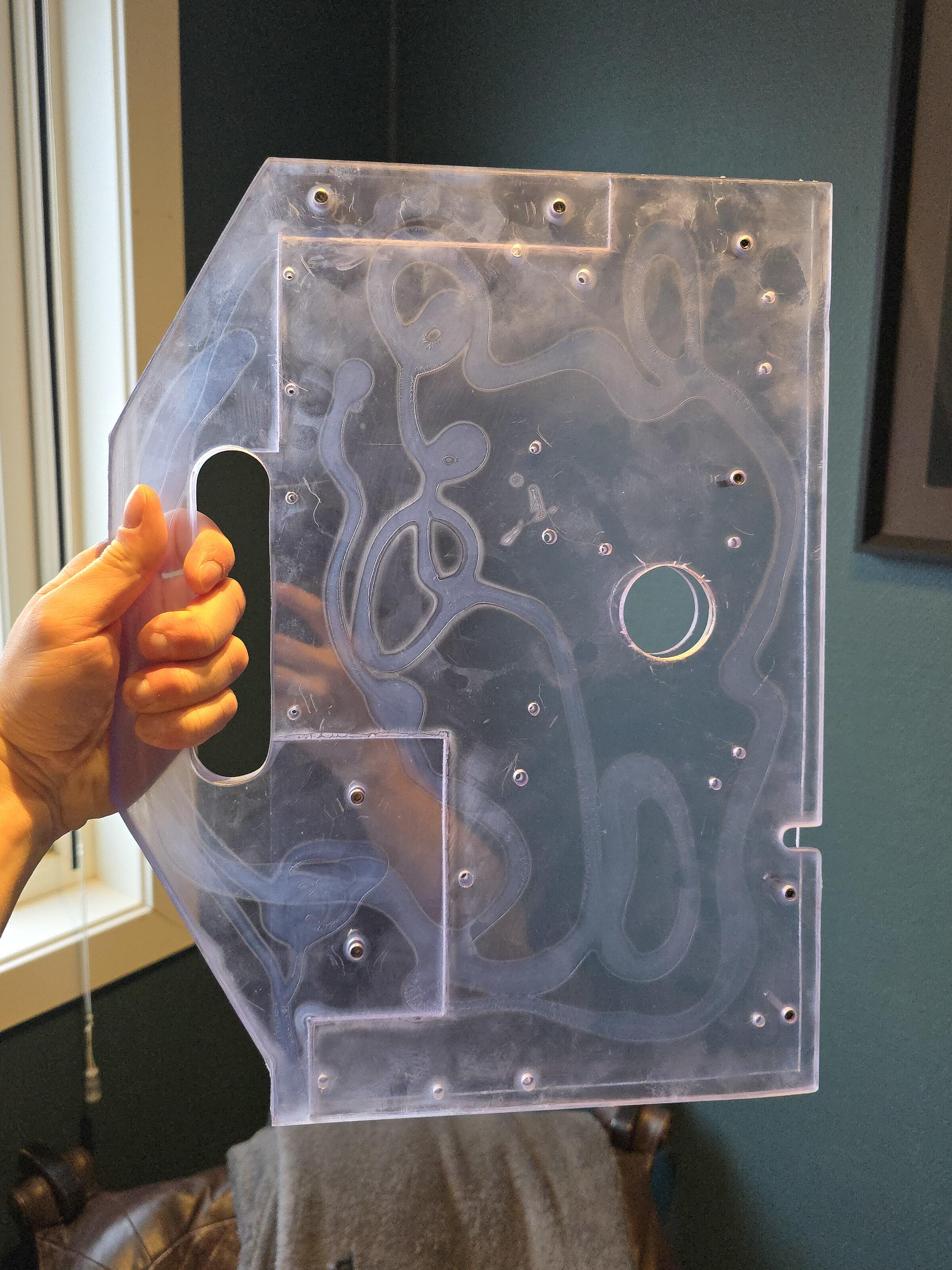
You may marvel at my squiggles.
Now, this is absolutely enough glue to serve its purpose. But — hear me out — what if; we added more glue?
You see, I had this voice in my head asking: "What if something catches onto the microscopic gap between two layers and rips it up? What if the device starts to warp and the edges separate due to bla-bla-bla...? What then, loser?"
The answer was obvious; paint the edges of all the plates with glue, to close of those tiny gaps.
So I went around the chassis with my tube of glue, and then — with a vinyl glove on — used my finger to smoothen out the glue against the edges.
Admittedly, it was a bit thick and remained rubbery for a couple of days. But turned out okay once it was time to start -
Sanding
The plan was only to sand the device in order to round the edges, remove excessive glue and for the paint to stick better.
But after rounding the handle and completing the surface-sand with my sander and some more sandpaper-aftercare by hand to get to the hard angles; It looked so good!
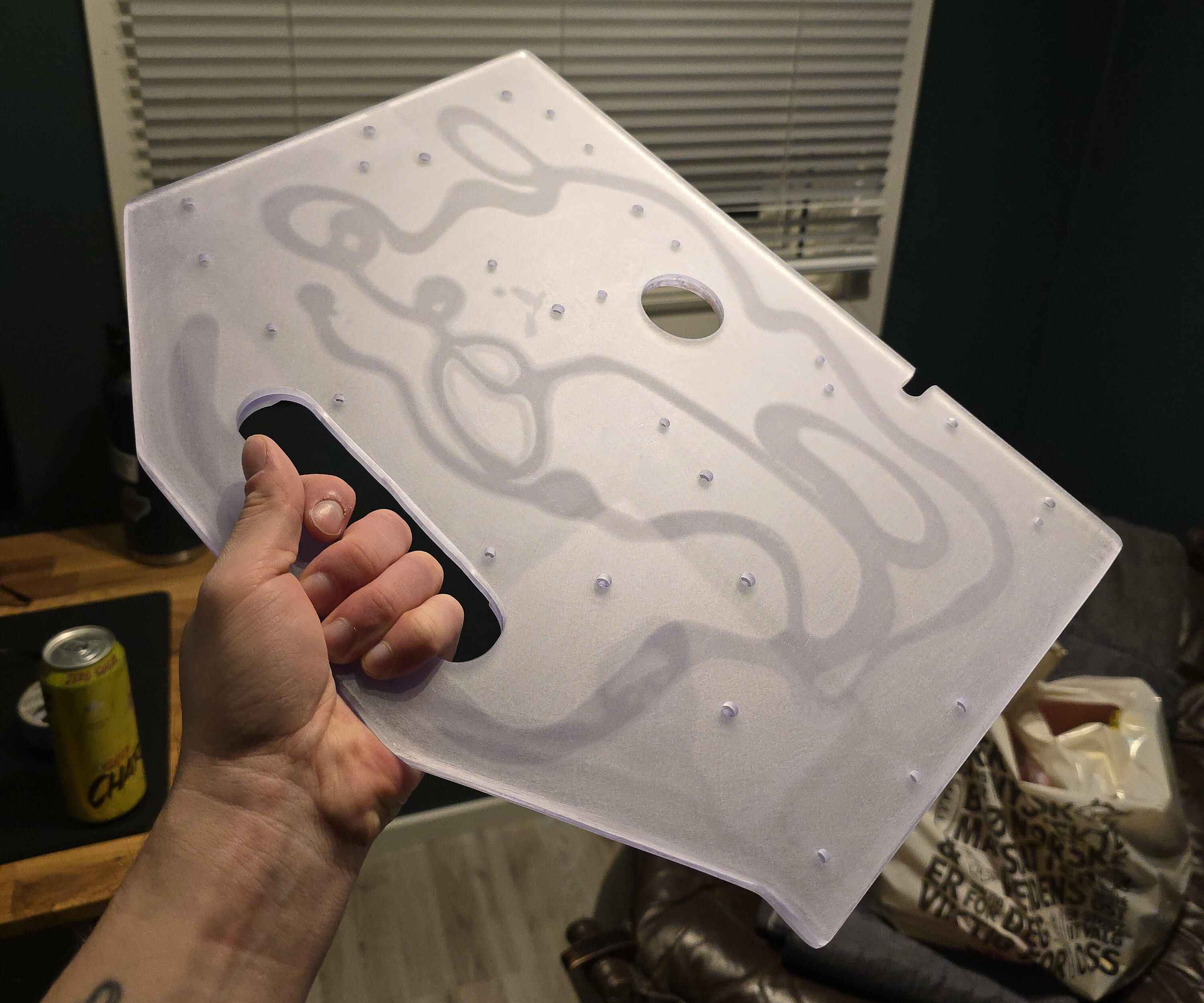
How could I, in good conscience, ruin this with paint. I had to reconsider.
Finally; Installing the Components
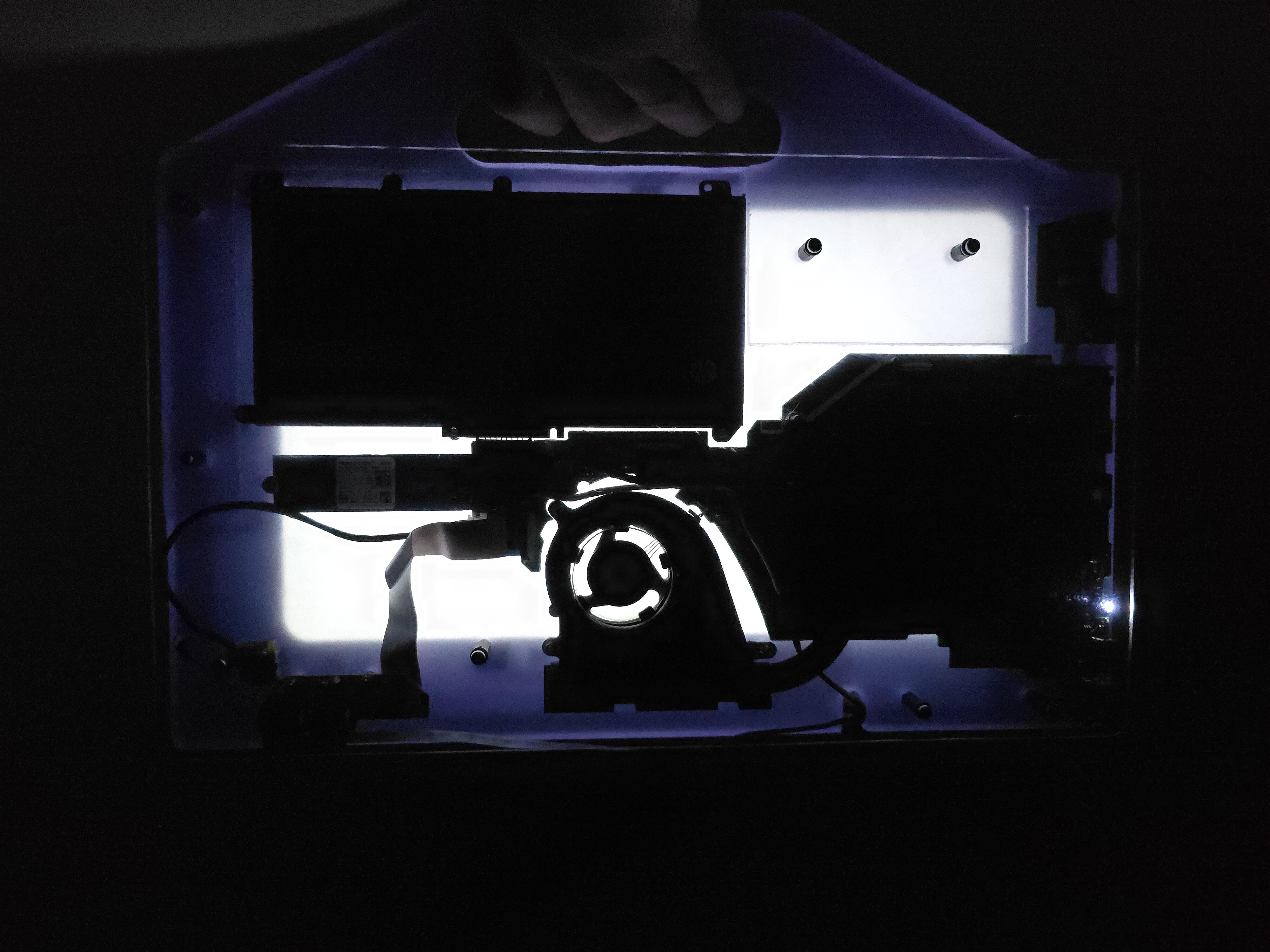
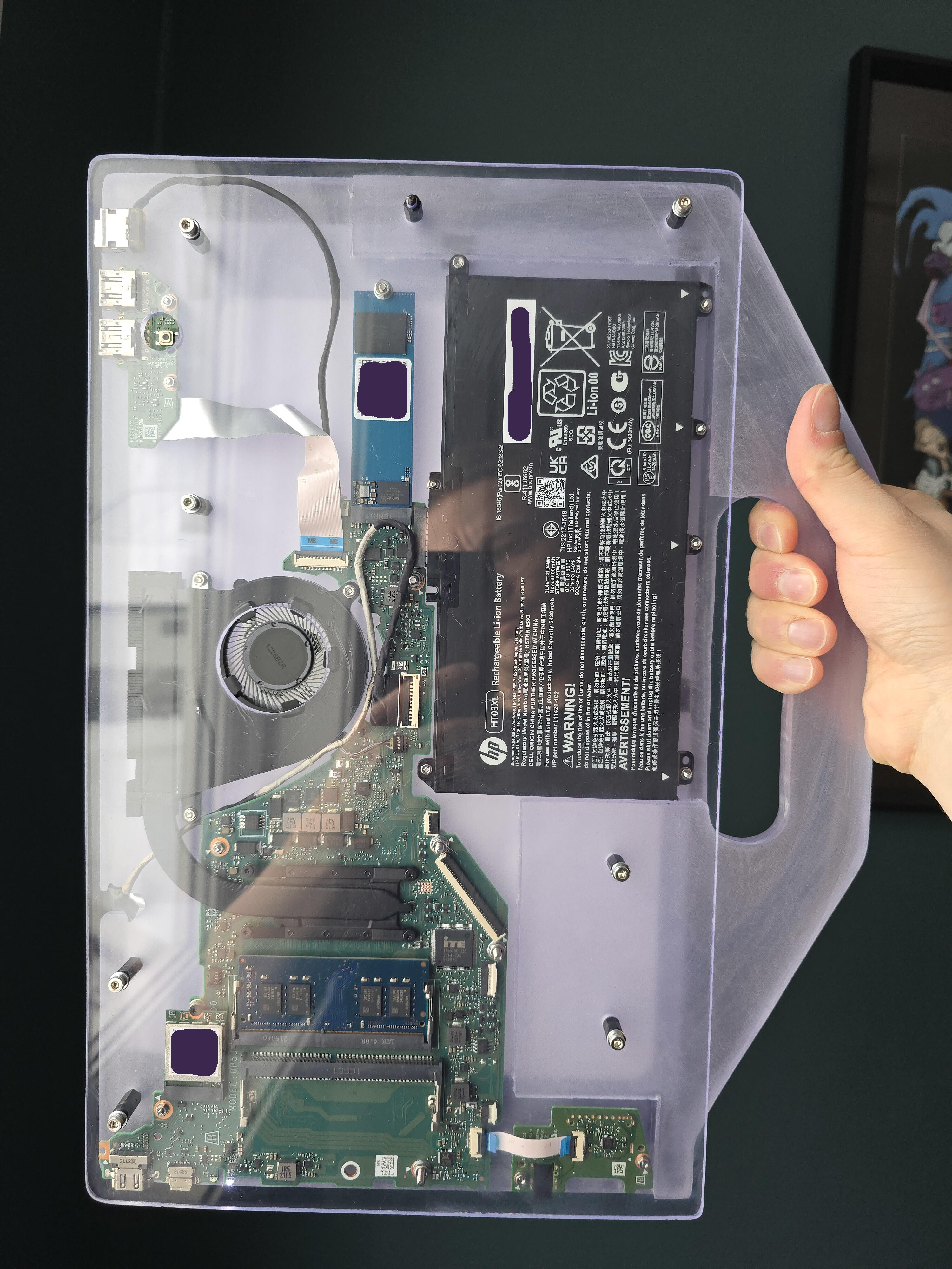
I went over my work. Making sure I hadn't forgotten anything or I wasn't unhappy with any angles or surfaces (I wasnt't). It was time to make all the parts come together.
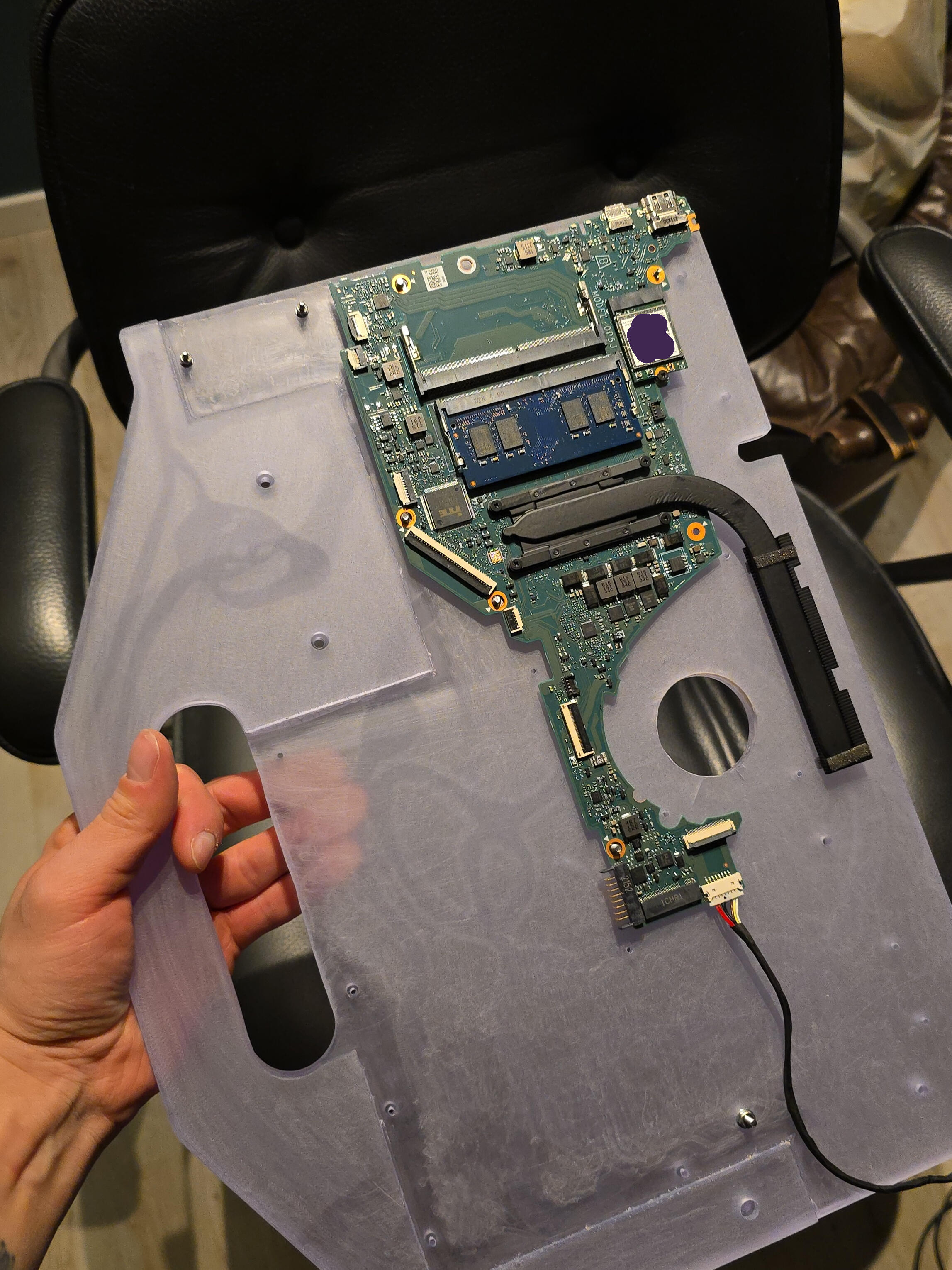
I started by aligning the motherboard; adding one washer at a time on the screws and seeing to that there was some gap for it to float above the acrylic. Some stacks of washers later, I realized; "Oh, I can just use nuts".
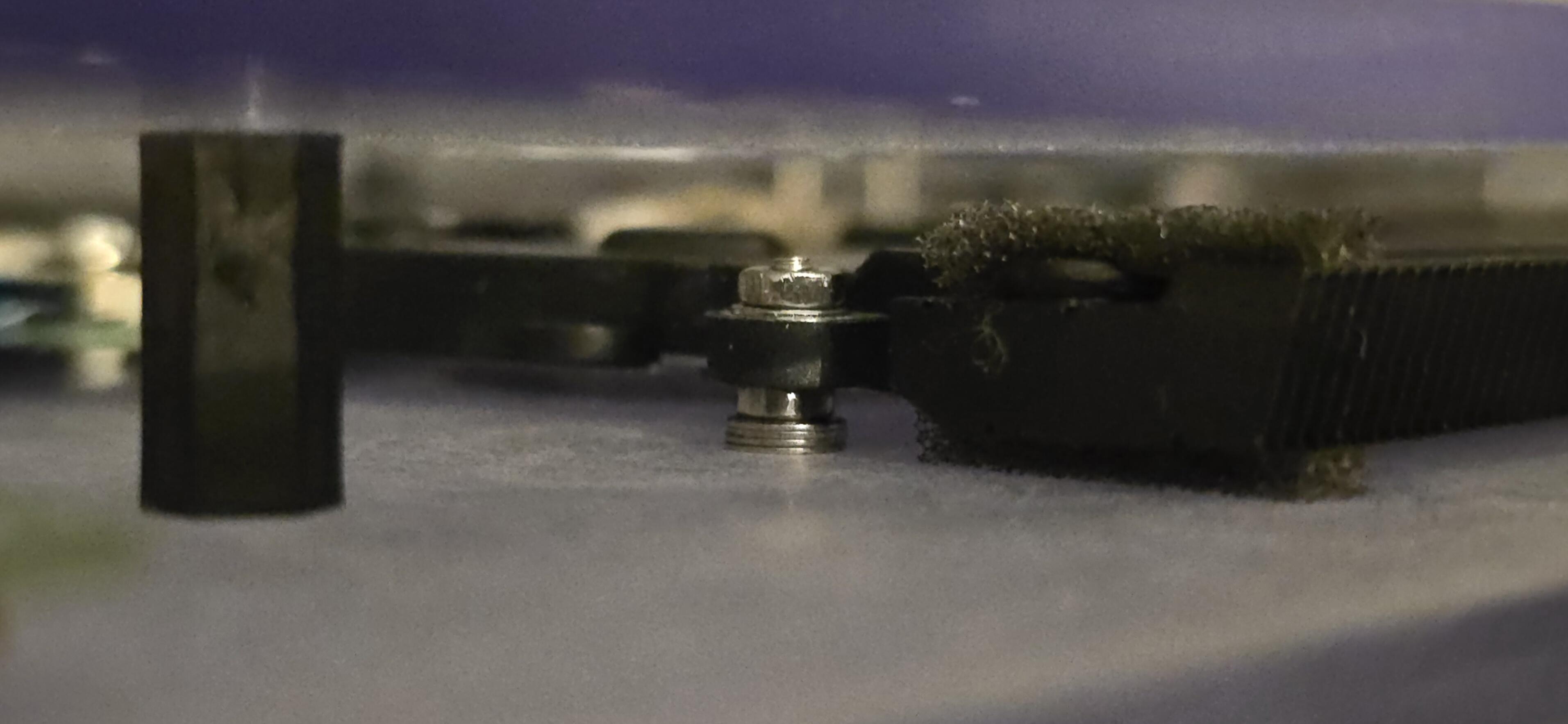
At least for the big stacks of washers. Some washers was still needed for proper alignment (see the stack for the fan below) where the nuts were too thick. I also used washers at the base of each screw-thread for some more surface and even pressure against the "brittle" acrylic, and the same for the PCBs.
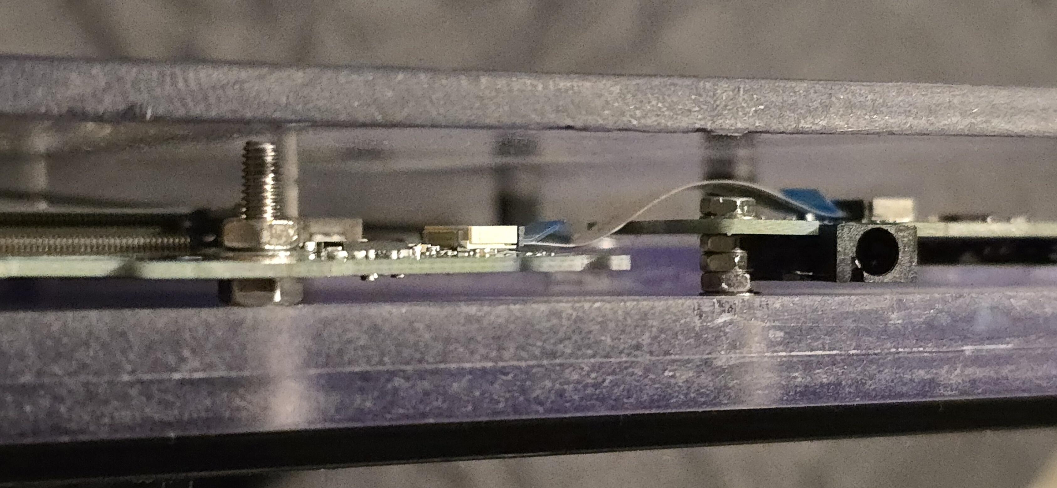
I then routed the cables as nicely as I could. The power-port was the dumbest one. It did not have any form of mounting-option for, like, a screw or such. It sat recessed in the corner of the laptop chassis with a metallic angle holding it in place. The angle had a screw holding it in place, but NOT the port itself.
This is where the double-sided tape — "Can probably be used to re-attach your head in a pinch" — comes into play.
I simply cut out a square and put it on there.
NOTE AFTER A COUPLE OF MONTHS OF THE PROJECT BEING COMPLETED: That thing isn't going anywhere.
Attaching the display went the same way. Eight small squares of double sided tape at the back of the display, but only at the metal "frame" on the outer part of the display, whereas in the middle; there was exposed, thin plastic. I didn't trust that plastic to not be damaged if I wanted to detach the display later. Another benefit of only taping the outer part of the back of the display; it would be easier to cut away with a thin knife, since the first piece of tape would be the hardest to detach if I wanted to do so.
First Boot
I forgot — or — I didn't really think of how I would turn it on. You see, the power button is one of those annoyingly small SMD pushbuttons. How would I get to it?
Another hole of course!
I used the largest drillbit in the set to drill a hole in the back-panel for my pinky finger to push the button through the back-panel. This comes with the added benefit of; no big-bad-bully can power on my machine, muah-haha!
Unless they get a pen or something, y'know.
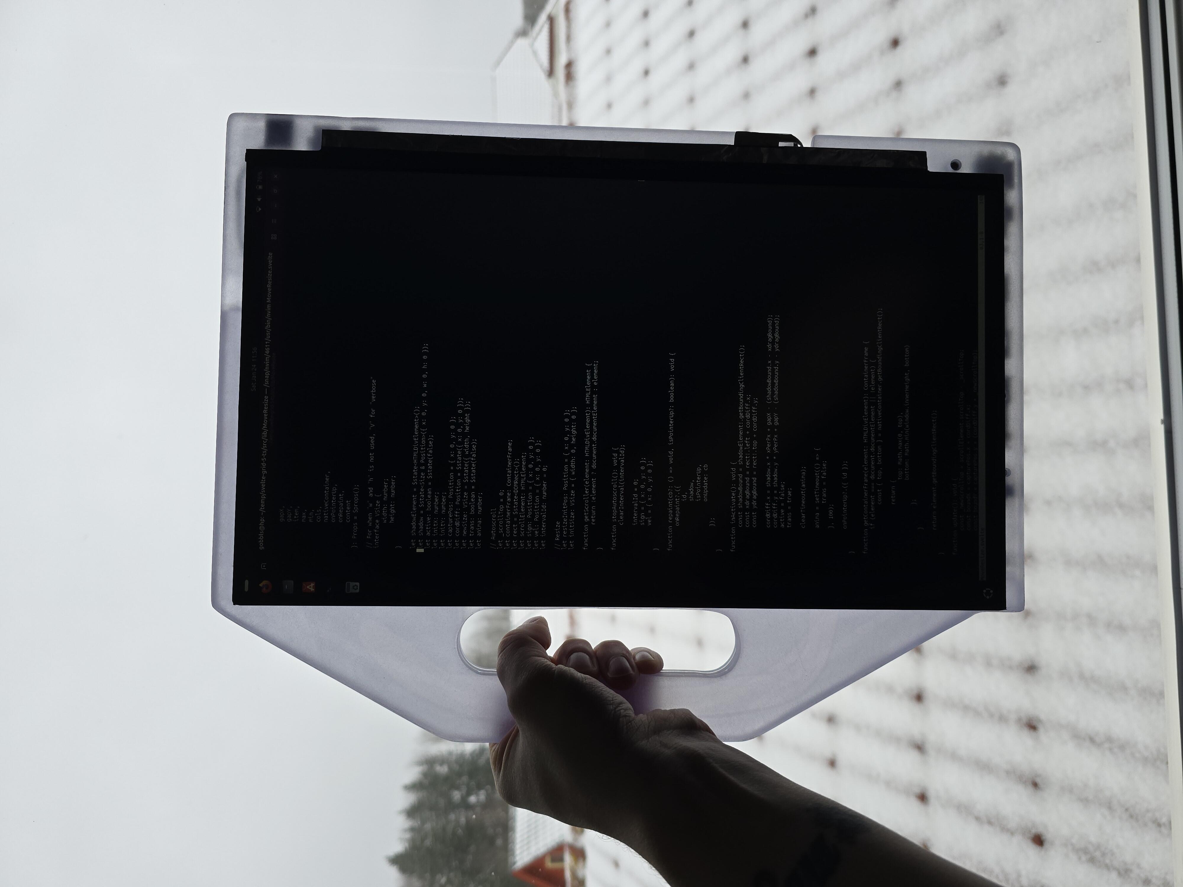
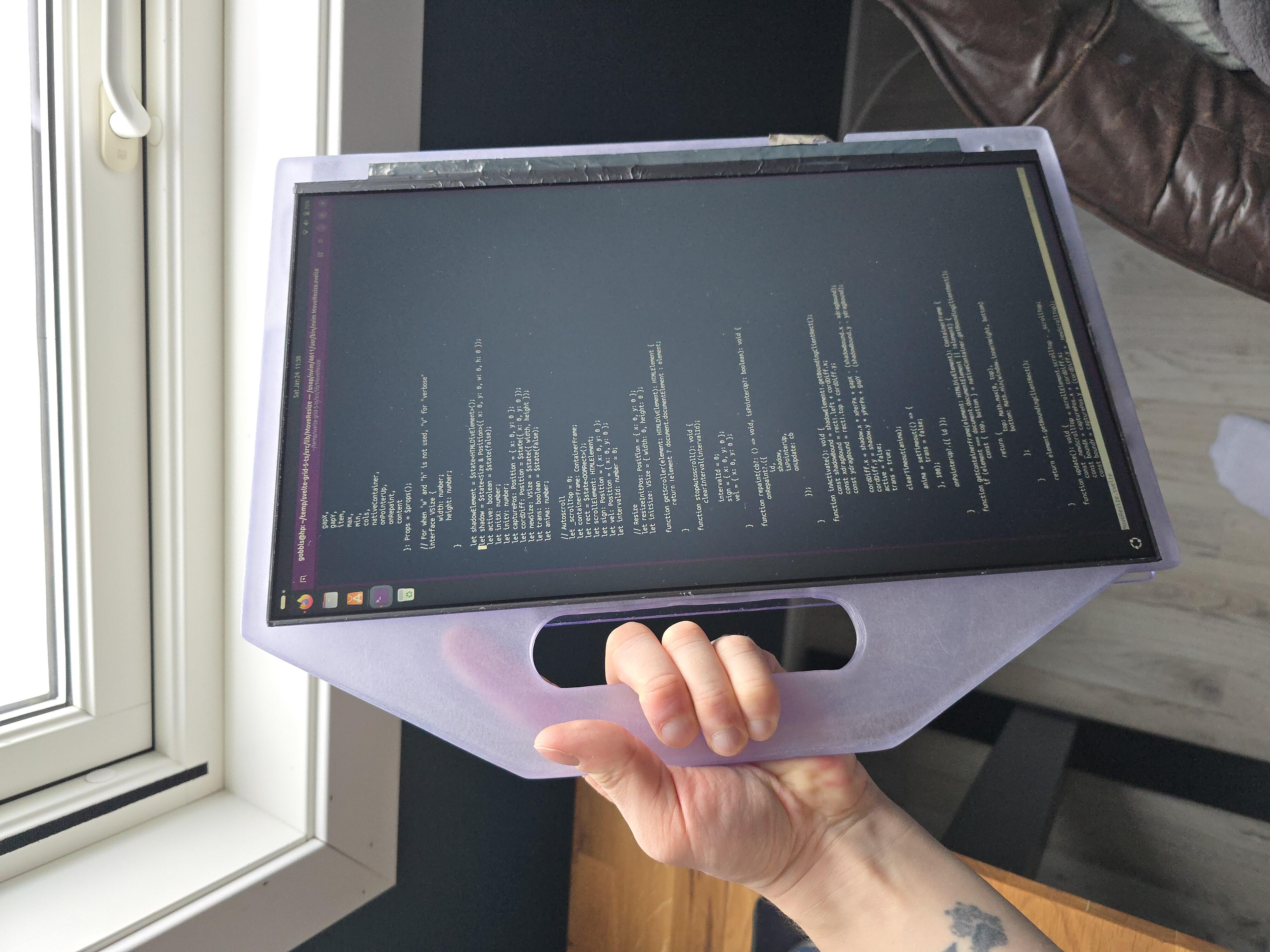
Anyways, when I first pressed the button, I saw the power-light light up, and seconds later, the HP logo showed. Then, I saw my Ubuntu login screen.
The display was intact, the fan was spinning. And damn, look at that cool light effect!
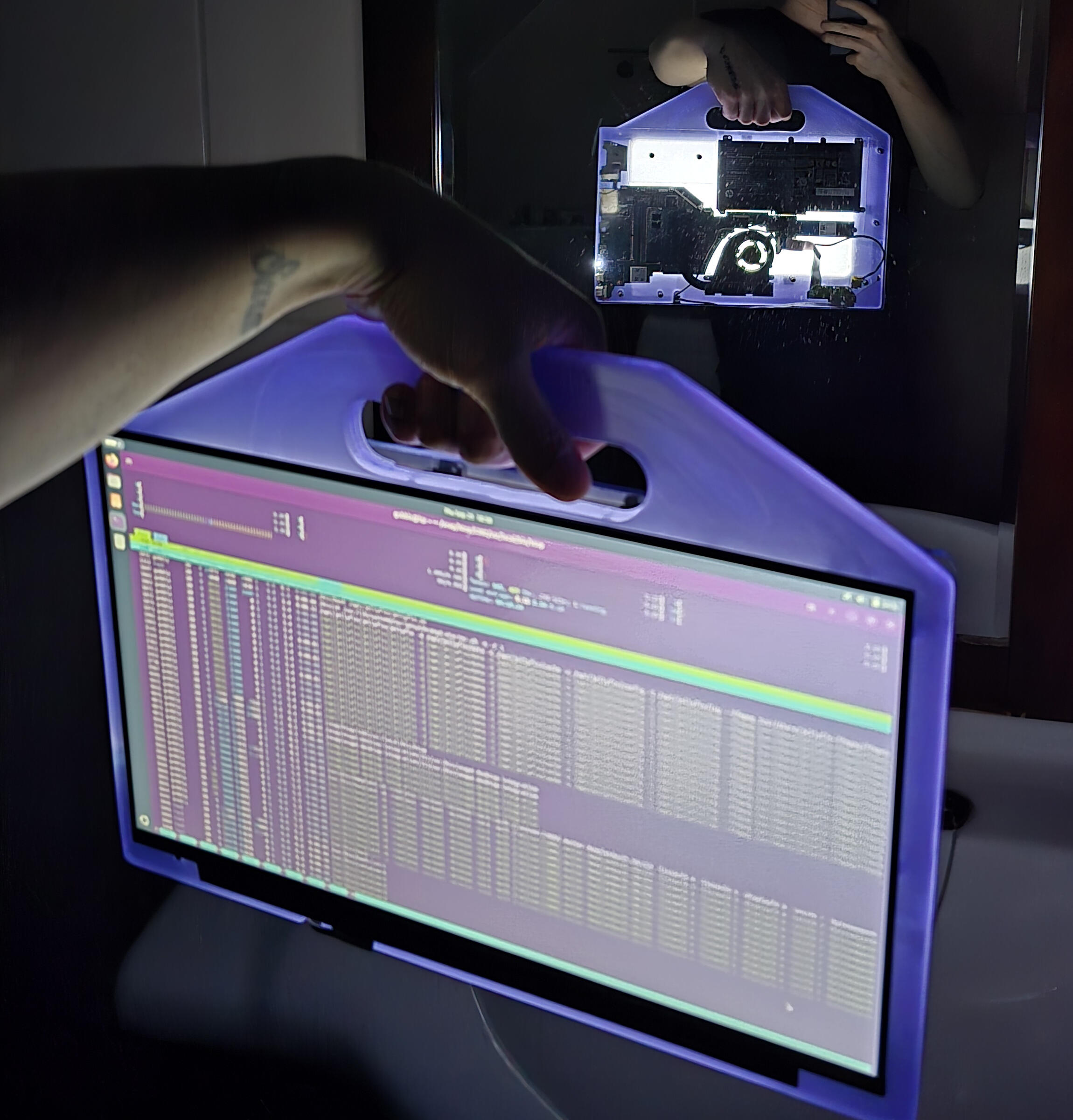
Who would paint over that?
I — I might actually later... But until then; I'll bask in its glowing glory.
Antennas
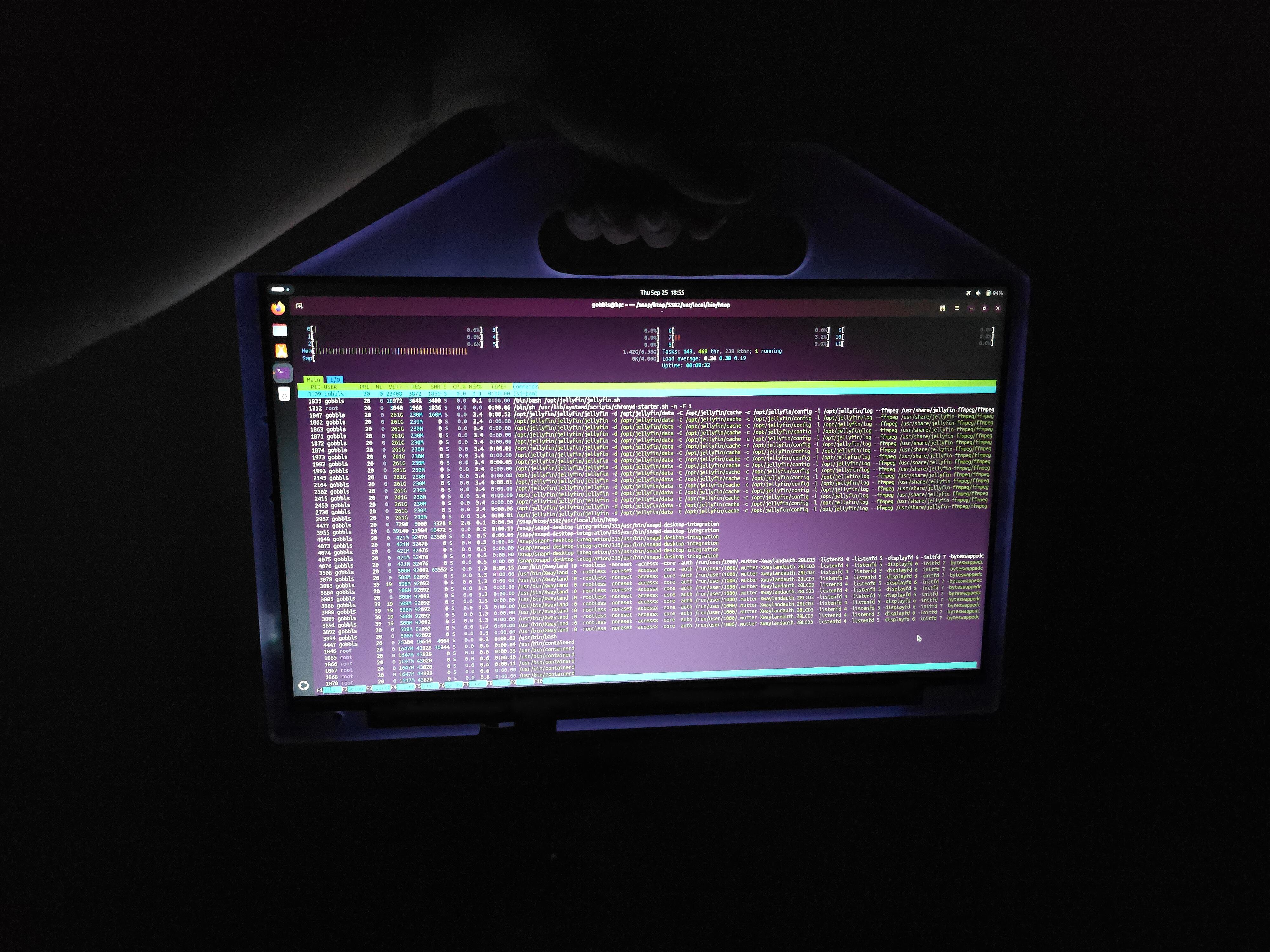
I had ordered the antennas, but they didn't show up until a couple of weeks after the project was "CoMpLeTeD". You can see them attached on the back in the last pictures — those small, black electrical-tape looking pieces with wires sticking out of them.
Until the antennas were installed, I used a USB-C-to-Ethernet adapter-cable, for wired internet.
Gallery
What I Would Have Done Different
- Not write this blogpost in pure HTML, that's for damn sure.
- As mentioned in the "planning" part; I should have adjusted the cutting-angles after adding the "chin" for future stands. It doesn't bother me, really, but it was a lazy — "meh, it'll be alright" — moment, and I should have held a higher standard for my craft than that.
Other than that; I'm very happy with both the process and result. And if I want to change anything — perhaps paint the chassis — it's will be really easy to disassemble the device for more customizations in the future.
I'm thinking of maybe installing a type of "frame" stand on the back of the device to keep it up-right on-the-go. And when I get access to a 3D printer; print a real button for the power-switch.
What I Learned
- about myself
More Realistic Expectations
My expectations for a completed project have become way more realistic from when I was a child, even a teen. When I planned larger LEGO projects as a child, I expected the final product to be exactly as imagined. And since a child has a very imaginative mind, I was very disappointed once the bricks came into place.
The size would be wrong, the colors would vary too much, the project wouldn't be sturdy enough for my liking, and the mechanisms too unpredictable. There were only a few, maybe even just two LEGO projects that went as planned.
And if woodworking projects were not of Expensive Furniture Quality, I had failed. I would fail to consider that I could not create what I wanted due to lack of proper tools and machinery, materials and years of experience.
But here, I was able to plan around what I had, what I needed, and the time to do so. And in the end, the outcome was satisfying.
Improved Willingness to Complete
Everytime I had some time on my hands, I went out into the garage and worked on the project, and would rarely sit idle doing other things while this was incomplete. I had "tunnel-vision", my complete attention, on this project and were getting a sense of accomplishment at every step of the way.
Some — maybe five — years ago, I would have multiple projects in the air and not really complete any of them. I wasn't capable of putting my focus entirely on a single project at a time. Making me unhappy with both the process and the final product. In late stages of a project, I had the feeling I just wanted to "get this over with" and move on to another project, continuing the cycle.
Final Thoughts
In the end, I'm ecstatic that this worked out. Enough so that I wanted to write about it, which is such a rare occurrence that I even wanted to tell the world about it through this post.
I should document my projects more often, for myself to find again later, and to track progress and my though process on problems I'm solving. So expect more "ramblings to the void" from me.
Thanks for reading!
- Aleksander N. Knoph
Footnotes
- 3,518 USD as of writing this. I bought it used, while still in ✨Premium, on-site💫 warranty and got pretty much the entire machine — except the bottom panel, battery and CPU fan — replaced due to faults I found that were covered under the warranty. My previous job involved doing HP and Lenovo warranty claims, so I know the song-and-dance needed to get stuff done. Funny enough, the same guys showing up on behalf of HP and Lenovo at my job, were the same guys showing up to my house to repair this device as well. I even had their phone numbers and names saved to my phone when they called about the ticket. It was a fun time. I'm still annoyed by the ports-thing though. Return
- It, curiously, doesn't have a name. Return